Specifications
Apollo GX50/60/65 Installation Manual
37
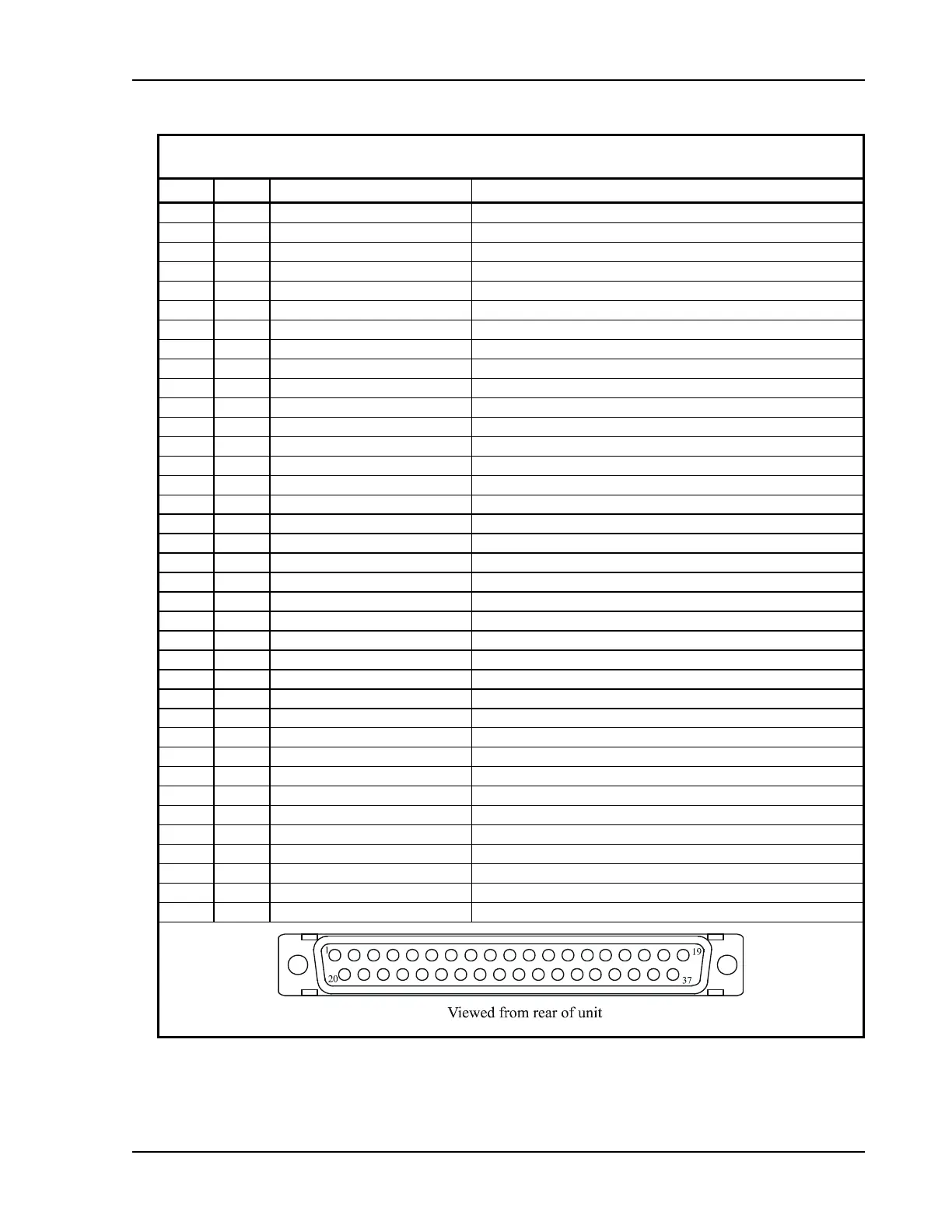
Table 3 Navigation Interface Connector Pinout
Pin # I/O Connection Function
1 I Power + main DC power input
2 I Power ground main power ground input
3 O Serial ground RS-232 signal ground
4 I RxD1 RS-232 channel 1 serial data input
5 O TxD1 RS-232 channel 1 serial data output
6 I Ext in 2 reserved
7 I Simulator select simulator mode, connect to ground for normal operation
8 I Flip/Flop
Remote comm frequency flip/flop input - GX60/65 only
9 O VDI Superflag VDI high level superflag output
10 O Nav + valid Nav low level valid flag output
11 O + FROM + From flag output
12 O + TO + To flag output
13 O CDI + Right CDI + Right output
14 O CDI + Left CDI + Left output
15 O ACTIVE Approach Active annunciator output (GX50/60 only)
16 O MSG Message annunciator output
17 O PTK Parallel track annunciator output
18 -- reserved do not connect
19 -- reserved do not connect
20 O Serial ground RS-232 signal ground
21 I RxD2 RS-232 channel 2 serial data input
22 O TxD2 RS-232 channel 2 serial data output
23 -- reserved do not connect
24 O reserved do not connect
25 O Ground signal ground connection
26 I Hold select Hold input (GX65 optional)
27 O Nav superflag Nav high level superflag output
28 O VDI + valid VDI low level flag output
29 O Ground valid flag ground connection
30 O VDI + Up VDI + Up output
31 O VDI + Down VDI + Down output
32 O Ground signal ground connection
33 O APPRCH Approach annunciator output (GX50/60 only)
34 O Hold Hold annunciator output (GX65 optional)
35 O reserved do not connect
36 O Power control Power control output
37 O Ground reserved