Specifications
Apollo MX20 Installation Manual
47
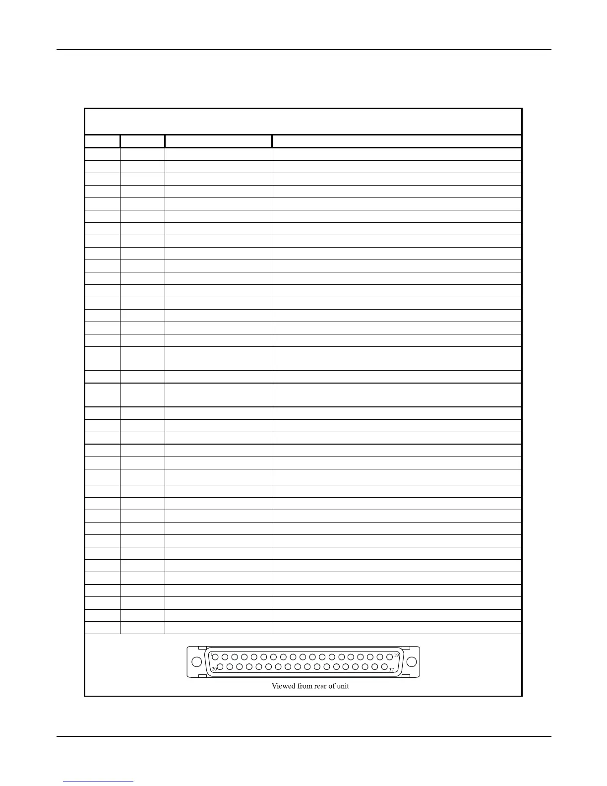
3.2 REAR CONNECTOR PINOUTS
Table 8 - MX20 Rear Panel Connector Pinout (J1)
Pin # I/O Name Comment
1 I Power + Main Aircraft Power Input (+10 to +30 VDC)
2 I Power ground Main Aircraft Power Ground
3 I Port 2 GND RS-232
4 I Port 1 IN RS-232
5 O Port 1 OUT RS-232
6 O Port 3 OUT RS-232
7 I Port 3 IN RS-232
8 O Port 4 OUT + RS-422
9 - NC Reserved
10 O Port 4 OUT - RS-422
11 I Port 4 IN + RS-422
12 I Power ground
13 - NC Reserved
14 I Input Flag 1 Discrete Input (Internally Pulled Up)
15 I Input Flag 3 Discrete Input (Internally Pulled Up)
16 I Heater Power + Auxiliary Heater Input (+10 to +30 VDC)
17 O 1 PPS OUT + 1 Pulse Per Second Output (RS422 Level). GPS timing is
referenced to the falling edge of +.
18 - NC Reserved
19 O 1 PPS OUT - 1 Pulse Per Second Output (RS422 Level). GPS timing is
referenced to the rising edge of -.
20 I Power ground
21 I Port 2 IN Port 2 RS-232 RxD
22 O Port 2 OUT Port 2 RS-232 TxD
23 I Port 1 GND RS-232
24 O Reserved (Power) NC In Aircraft Install
25 I Port 3 GND RS-232
26 I Port 4 IN - Port 4 RS-422 RxD -
27 I Reserved (Ground) NC In Aircraft Install
28 I Reserved (Data) NC In Aircraft Install
29 I Reserved (Clock) NC In Aircraft Install
30 - NC Reserved
31 - NC Reserved
32 - NC Reserved
33 I Input Flag 2 Discrete Input (Internally Pulled Up)
34 I Input Flag 4 Discrete Input (Internally Pulled Up)
35 - NC Reserved
36 I External Power Switch External Power Switch (Gnd to Turn On)
37 - NC Reserved