16
Helpful Hints (continued)
G1SINGLE OPERATION MANUAL
© 2023 APPION INC. - ALL RIGHTS RESERVED
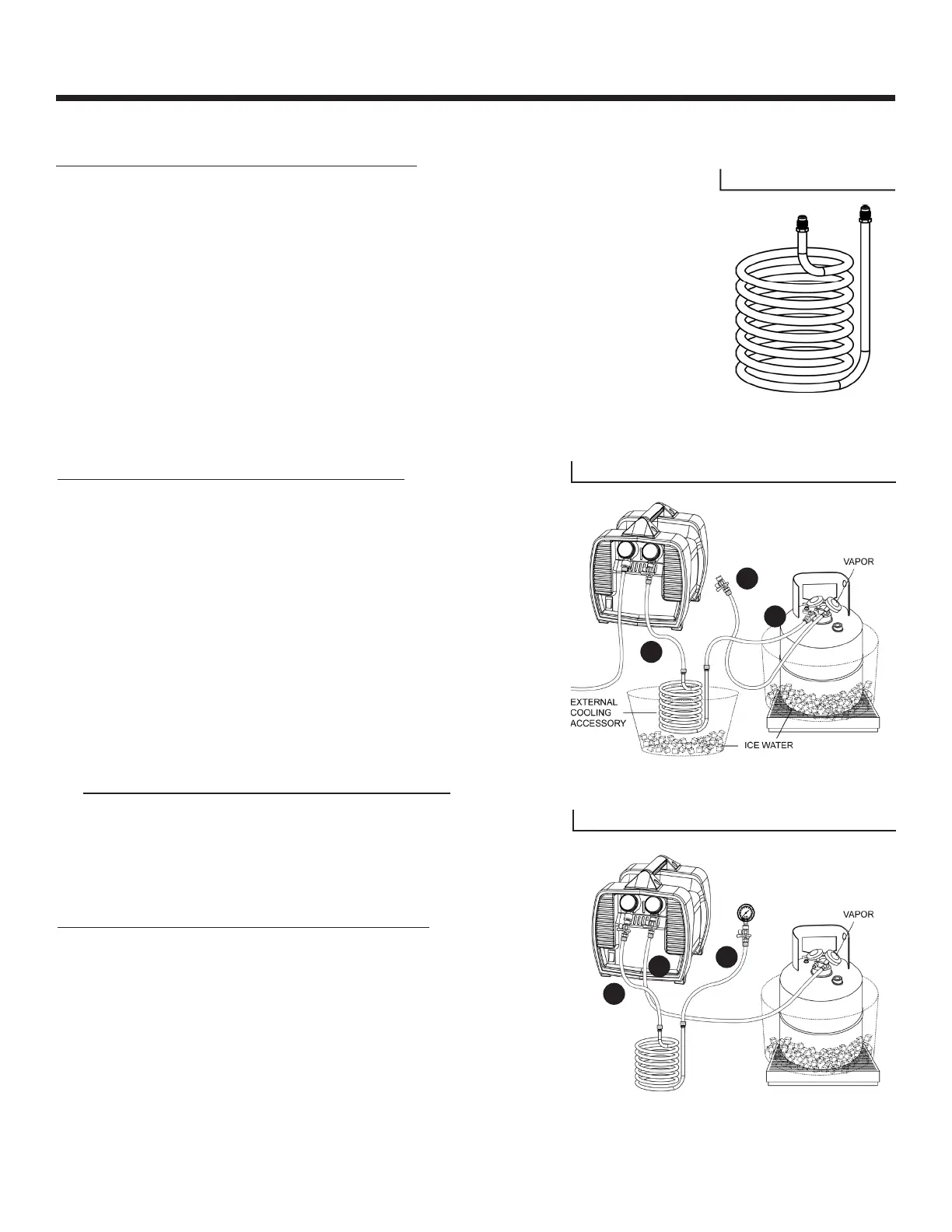
How to Make an External Cooling Accessory:
Making an ECA uses the same tools as you would use when installing an AC/R
system. You will need 50 feet of 1/2” (OD) copper tubing, and two (2) 3/8” FL Service
Valves. Connect the service valves to each end of the copper tubing with solder
using industry practices. Then, coil the tubing around a pipe or round object of
at least 8” inches in diameter, and maintaining about 1/8” spacing between each
coil. Leave about 2 feet of the copper tubing straight, and bend it upwards, so that
both extend above the “coiled area,” as in Diagram 9. Prior to using the ECA, verify
pressure and vacuum tightness using the same methods as on an AC/R system.
Alternative: A 50 foot, 1/2in (OD) copper Immersion Wort Chiller with two (2) 3/8in
FL service valves fitted to the ends of the copper tubing can also be used in place of
making your own.
How to Use an External Cooling Accessory:
Using a 5-gallon bucket (or equivalent container), submerge
50% of the ECA in water before adding ice. Continue to add ice
until the ECA is submerged below the ice by at least 3 inches.
This will help keep the ice water cooled as the heated vapor
travels through the ECA.
Important: If the ice melts, replenish the ice as needed to maintain
maximum cooling throughout the recovery process.
Connect the ECA and hoses equipped with ball valves as shown
in Diagram 10. Submerge the ECA in a bucket of ice water (as
described above). Close the ball valve on Hose “C”, and open
the ball valves on Hose “A” and Hose “B”, as shown in Diagram
10. Proceed with the Standard Recovery Procedure as described
on Page 9, starting from Step 2, and continuing through Step 9
(substitute the Recovery Cylinder Liquid Port in Step 2).
WARNING: Aer recovery is complete, the ECA and Hoses A, B and
C will contain high pressure refrigerant.
To recover the residual refrigerant from the ECA:
1. Close the Recovery Cylinder liquid valve, and the ball valve at
the end of Hose “A”.
2. Disconnect the hoses from the G1Single input/output.
3. Connect the hoses as shown in Diagram 11.
4. Open the Recovery Cylinder vapor valve, and all 3 ball valves.
5. Repeat Steps 6-9 from Page 9 to finish the recovery.
Diagram 9
Diagram 10
Diagram 11
A
A
B
B
C
C