POS MV V5 Installation and Operation Guide
Theory of Operation
Copyright © Applanix Corporation, 2017
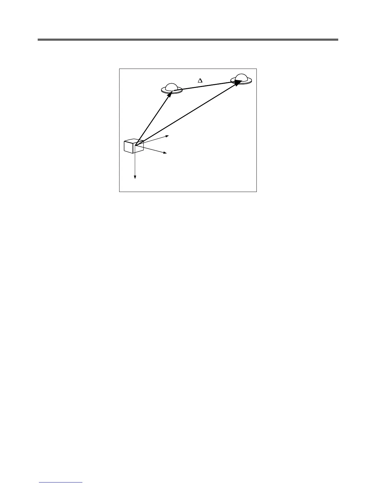
Figure 91: IMU and GNSS Antenna Geometry
To compute the heading of the IMU (that is the heading of the x-axis of the IMU body frame) GAMS must
have the components of ∆R
AB
resolved in the IMU body frame (the surveyed antenna baseline vector).
These components and the length of the vector are the GAMS installation parameters.
You can measure the GAMS installation parameters using a direct survey method, or POS MV can
calibrate them automatically as part of an antenna installation calibration.
Both methods have advantages and disadvantages:
• Direct measurement of the parameters using precision survey techniques provides the best
heading accuracy and allows POS MV to deliver full operational performance immediately.
However, it also involves a laborious and complicated survey exercise using qualified survey
personnel, special equipment and detailed engineering drawings of the vessel.
• Conversely, a POS MV installation calibration provides calibration parameters that are initially
less accurate. However, the system can perform the procedure during normal survey operations
without the need for any special additional equipment or personnel. You can improve the
accuracy of this type of calibration by empirical methods, or by making a direct comparison with
another heading instrument such as a gyrocompass.
Refer to Initial GNSS Configuration on page 4-21 for instructions to complete an installation calibration.
Carrier Phase Differential Position
GNSS measurements possess long-term stability and an accuracy that, with DGNSS, can be within a few
metres. However, the measurements do not possess sufficient accuracy to allow a precise determination
of the geographic antenna baseline vector.
IMU body
frame
R
A
R
B
R
AB
Antenna A
z
b
z
b
y
b
y
b
x
b
x
b
Antenna B