ENGINE
RSV mille
3 -90
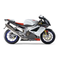
3.7.6 ASSEMBLING THE OIL PUMP
Carefully read 0.2.1 (PRECAUTIONS AND GENERAL
INFORMATIONS).
Make sure the LOCTITE
®
product does not get inside
the suction pump hole.
◆ Apply a thin film of LOCTITE
®
574 on the gasket sur-
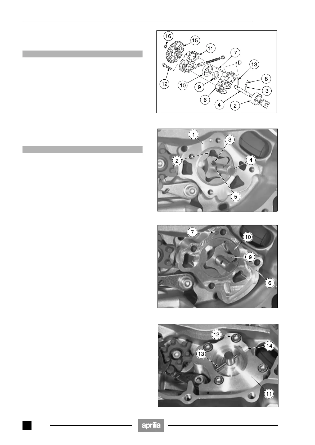
face (1) of the oil pump casing.
◆ Insert the duly oiled external rotor (2) in the slot in the
casing.
NOTE The reference point must face down (towards
the engine casing).
◆ Insert the pin (3) in the last hole at the bottom of the oil
pump shaft (4).
◆ Insert the internal rotor (5) in the oil pump shaft (4), with
the housing slot facing up.
◆ Insert the oil pump shaft (4) in the casing, complete with
internal rotor.
Make sure the LOCTITE
®
product does not get inside
the pressure pump hole.
◆ Apply a thin film of LOCTITE
®
574 on the external gas-
ket surface of the oil pump casing (6) and install it on
the oil pump shaft (4).
◆ Fasten the oil pump casing (6), complete with pin (7),
inside the casing.
◆ Insert the pin (8) in the central hole of the oil pump
shaft.
◆ Insert the duly oiled internal rotor (9) of the pressure
pump on the oil pump shaft, with the driving groove fac-
ing down.
◆ Insert the duly oiled external rotor (10) in the oil pump
casing.
◆ Fasten the oil pump cover (11) with the four T.C.E.I.
screws (12).
Driving torque of screws (12): 11 Nm (1.1 kgm).
◆ Insert the pin (13) in the hole of the oil pump shaft.
NOTE The oil pump cover features a groove (14) ena-
bling the pin to be fitted.
Line the pin up with the centre of the oil pump shaft.
D = LOCTITE
®
574.
 Loading...