User Manual
TRANSMITTER-PLC INSTALLATION
Transmitter-PLC power supply must be on same AC branch circuit as inverter to meet rapid shutdown
requirements.
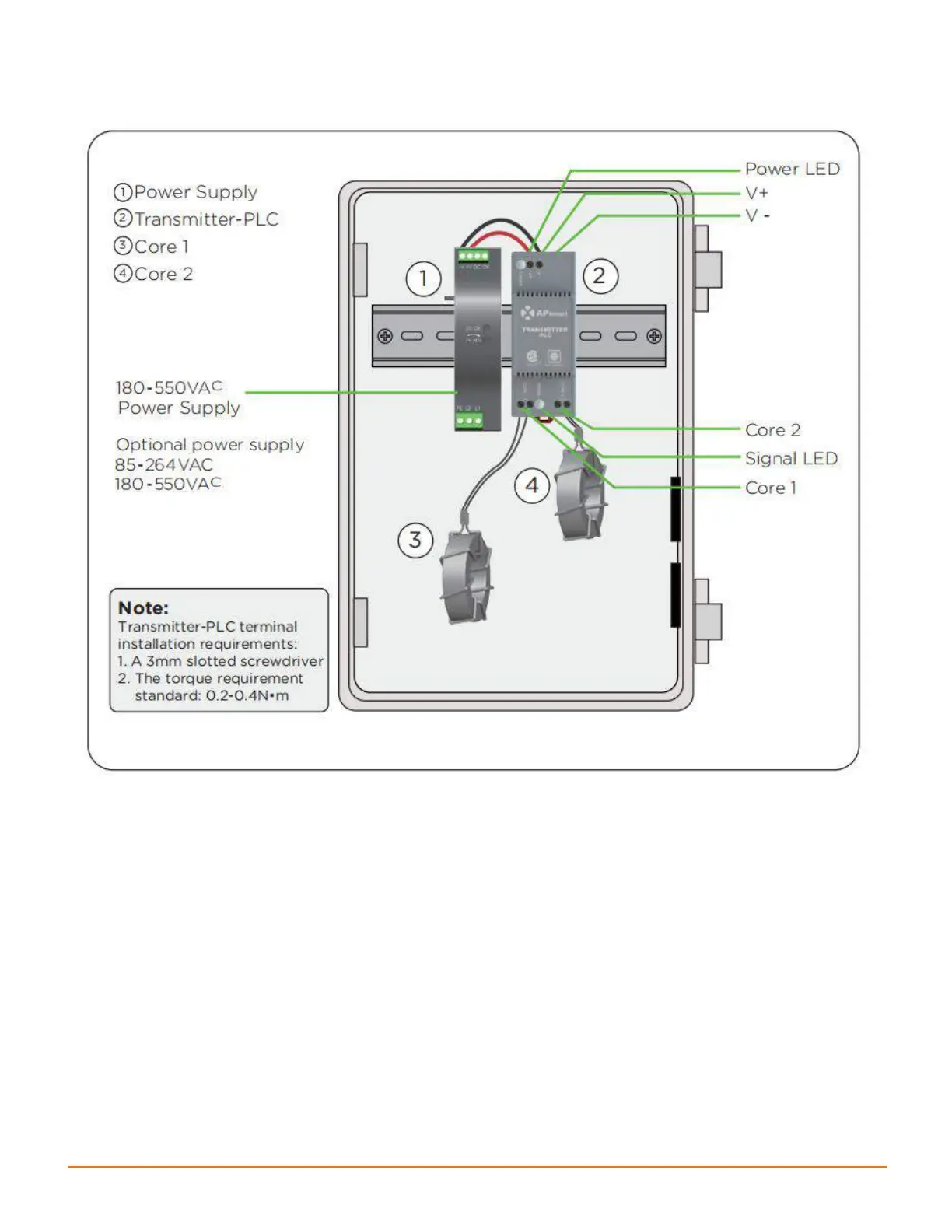
During operation, the Power LED should be lit and the Signal LED should be blinking. If the Transmitter-
PLC fails to work, the Signal LED will not be blinking. If the Power LED is also not lit, check the power
supply first.
Note: Install the RSD-D before powering on the Transmitter-PLC.
• Mount Transmitter-PLC and power supply on DIN rail
• Connect DC leads from power supply to Transmitter-PLC
• Connect single/dual core(Core 1 and Core 2) to Transmitter-PLC
Place rapid shutdown system label no more than 1m (3ft) from Transmitter-PLC or AC disconnect if not at
same location.
Note: If there is only one core needed, connect using Core 1 terminal.