APsystems ECU-B Installation/User Manual
Maximum monitoring 4 PV Modules.
4. ECU-B User Interface
Green light indicates the mobile phone is connected to the
ECU-B.
Grey light indicates the mobile phone fails to connect to the
ECU-B.
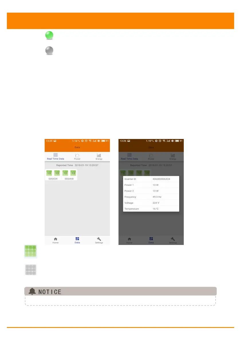
4.5 Data
4.5.1 Real Time Data
This page shall display the added inverter. According to different
models of inverter, each inverter would have the corresponding
modules displaying the real time power.
Click "Module", the detailed information of the inverter shall be
displayed, including inverter ID, PV module power, grid voltage,
frequency and temperature.
Green panel indicates the inverter is successfully connected.
Grey panel indicates the inverter is disconnected.
4.