APsystems ECU-B Installation/User Manual
2. Interface Explanation
2.3 Power Connection Port
The power connection port connects power through the power adapter.
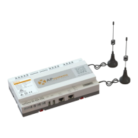
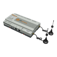
2.4 Antenna
The antennas in the package should be connected to ECU-B. One antenna is
used for the communication between ECU-B and inverters, the other
antenna is used for the Wi-Fi connection between ECU-B and router.
2.5 USB port
The USB interface is reserved.
2.6 AP
Press the AP button to turn on AP. Then the ECU-B can be scanned by
phone. ECU-B will turn off it automatically in one hour.
Figure 3
2.7 LED1
LED1 will be on When the ECU-B works well.
2.8 LED2
LED2 will be on When the ECU-B connects to the sever.