ECU-C Installation/User Manual
3.Hardware Installation
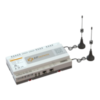
Figure 10
Option 2: Wireless Connection.
Use ECU-C internal WLAN (see Managing the WLAN Connection, pg. 23).
Option 3: Using a PLC bridge:
1) Make sure the LAN cable is connected to the network port on the bottom
of the ECU-C.
2) Connect the LAN cable to the “send” unit of the PLC bridge.
3) Connect a LAN cable from the “receive” unit of the PLC bridge to a spare
port on the broadband router (refer to the bridge users manual for
specific operating instructions).
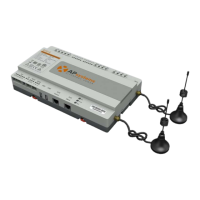
Figure 11
The network cable in the package can be used to connect the ECU-C with
PC directly. One side is connected with the ECU-C and the other side is
connected with the PC. Then change the IP address and the network
mask to 192.168.131.1 and 255.255.255.0, respectively.
1. A PLC bridge uses the power line to communicate and requires both a
“send” and “receive” unit.
2. The quality and length of the LAN cable will affect the ECU-C
communication quality. You can use a Switch to enhance the
communication quality if necessary.