ECU-C Installation/User Manual
2.Interface Explanation
Interface Layout
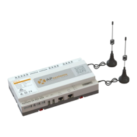
The ECU-C interface includes, (figure 2)from left to right, are AC Input、
Production CT、Grid CT、Relay Output、Relay Feedback Input、Reset.
(figure 3)from left to right, are Port、DC、RS232、RS485、USB1、USB2、RJ45、
Internet
、
RJ45 Signal
、
AP.
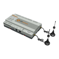
(figure 4)from left to right, are antenna(Zigbee)、antenna(Wifi).
Reset Relay Feedback Input Relay Output Grid CT Production CT AC Input
Figure 2
Port DC RS232 RS485 USB1 USB2 RJ45 Internet RJ45 Signal AP
Figure 3
Antenna(Zigbee) Antenna(Wifi)
Figure 4