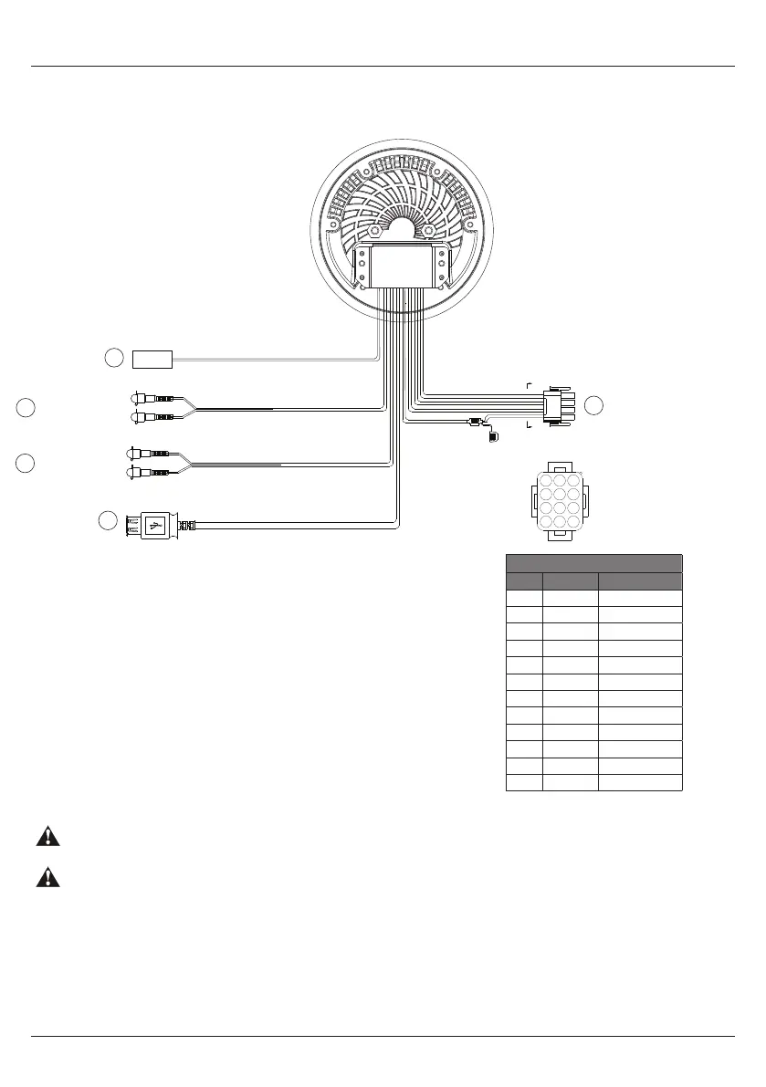
1.3 Connections Diagram
All open wire connections should be soldered and protected against water and dust for best long-term performance.
No lower than a 2 Ohm speaker load should be used or damage may occur to the stereo. Make sure the polarity of
speakers is connected correctly.
12-pin Watertight Harness*
Pin No. Wire Color Description
1 Green LR Speaker (+)
2 Green/Black LR Speaker (-)
3 Red Acc (+12V)
4 White LF Speaker (+)
5 White/Black LF Speaker (-)
6 Yellow Battery (+12V)
7 Gray RF Speaker (+)
8 Gray/Black RF Speaker (-)
9 Blue Power AMP Remote
10 Violet RR Speaker (+)
11 Violet/Black RR Speaker (-)
12 Black Ground
1
4
7
10
2
A- A
5
8
11
3
6
9
12
A
A
1
2
4
3
5
AM/FM Radio Antenna Jack
RCA Auxiliary Inputs (Black)
RCA Auxiliary Outputs (Gray)
USB Input (Black)
12-pin Watertight Harness
Fuse 15A
Right Channel (Red)
Left Channel (White)
Right Channel (Red)
Left Channel (White)
Getting Started GP1 WATERPROOF STEREO
4www.aquaticav.com