Flex ECO 6S/X MRX Instruction Manual
August 2017 v1.0
Page 17 of 34
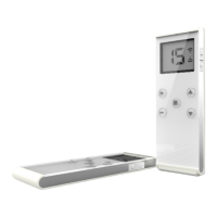
4.1.6 Infrared Programming
Other custom functions and settings not listed in this manual can be
programmed via the infrared IR programmer unit, such as the system
serial number, frequency range, new and updated functions, plus many
others. Please contact ARC representative for more details.
4.1.7 Pushbutton Function Settings
1) Press down the STOP button (transmitter power off).
2) Press and hold PB3 and PB4 at the same time.
3) Reset the STOP button by rotating it clockwise or counter
clockwise, it will pop up (transmitter power on).
4) Let go PB3 and PB4 at the same time (entered Pushbutton Function mode). LED-B
lights up during pushbutton function setting mode.
5) The Status LED displays current pushbutton function setting with orange, green and
red blinks. An orange blink represents the hundreds (+100), a green blink represents
the tens (+010) and a red blink represents the units (+001). For example, 1 orange
blink followed by 2 green blinks and 5 red blinks is pushbutton function no.125.
Pushbutton function number with “0” is represented by no orange, green or red blink.
For example, 1 orange blink followed by 5 red blinks is pushbutton function no.105.
6) Set pushbutton function number by pressing PB3 to increment the hundreds (+100),
PB2 to increment the tens (+010), PB1 to increment the units (+001), and PB4 to reset
(000 - constant orange). For example, press PB3 one time, PB2 four times, PB1 six
times is pushbutton function no.146 (Status LED blinks 1 orange, 4 greens and 6 reds)
7) Exit Pushbutton Function mode by pressing down the STOP button (transmitter power off).
Toggled Pushbutton with LED Indication – Standard Right/Left
Pushbutton Configuration
Set pushbutton toggled function (latching output relay) with LED
indications. LED A and LED B shown inside the shaded box
illustrates which LED on the transmitter lights up when the
designated pushbutton is pressed.
Function
Number
Display Type PB1 PB2 PB3 PB4 PB5 PB6
1
1 Red LED A Normal Normal Normal Normal Normal
2
2 Reds Normal LED B Normal Normal Normal Normal
3
3 Reds Normal Normal LED A Normal Normal Normal
4
4 Reds Normal Normal Normal LED B Normal Normal
 Loading...