EasyManua.ls Logo

ARC Flex Series - User Manual

ARC Flex Series
37 pages
Print Icon
To Next Page IconTo Next Page
Loading...
FLEX8ES
User’s Manual
FCC Version

Table of Contents

Questions and Answers

  • B
    Brendan GreenAug 6, 2025
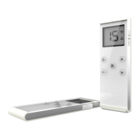
    What to do if there is no AC power to the ARC Flex Remote Control receiver?
    • A
      andrewsevelynAug 6, 2025
      If there's no AC power to the ARC Remote Control receiver, consider the following: * **Incorrect input voltage:** Make sure the source voltage is set correctly. * **Blown fuse:** Check for any blown fuse. * **Incorrect wiring:** Check the input voltage connection.
  • N
    Nathan WilsonAug 13, 2025
    What to do if ARC Flex Remote Control transmitter button doesn't respond (damaged hardware)?
    • C
      campbelljoyceAug 13, 2025
      If the ARC Remote Control transmitter button isn't responding and you suspect damaged hardware: 1. Check the SQ display on the receiver unit. If it doesn't light up when the push button is pressed, either the transmitting or receiving module is defective. Replace the transmitting module first. If the SQ display still doesn't light up, replace the receiving module. 2. If there's still no response after replacing the modules, replace the transmitter encoder board. If it still doesn’t work, the decoder module is defective.
  • J
    Joy WilliamsAug 21, 2025
    How to fix ARC Flex outputs that don't correspond to the transmitter?
    • Q
      qcarterAug 21, 2025
      If the ARC Remote Control outputs do not correspond to the transmitter, check the system wiring again. Please refer to the output contact diagram inside this manual or on the receiver cover.
  • S
    Scott JonesOct 29, 2025
    Why ARC Flex Remote Control transmitter push button is not responding?
    • S
      Stephanie NguyenOct 29, 2025
      The ARC Remote Control transmitter push button may not respond due to several reasons: * The transmitter battery power may be low: Check the transmitter battery level. * The emergency stop button may have been activated prior to startup: Ensure the red emergency stop button is elevated before turning on the transmitter. * The transmitter push button functions may be locked: Initiate the Start command by rotating the power key-switch to the START position. * The system RF channel may be incorrect: Verify that the transmitter handset and receiver unit both have the same channel. * The system serial number/ID code may be incorrect: Ensure that the transmitter handset and receiver unit both have the same serial number/ID code. * The system may be out of range: Confirm that the ope...

Summary

Introduction

Radio Controlled Safety

General System Information

Transmitter Handset Overview

Details the external components and illustrations of the transmitter handset.

Receiver Unit Overview

Details the external components and illustrations of the receiver unit.

Function Settings

Transmitter Handset Configuration

Covers system channel settings and push button functions for the transmitter.

Transmitter Channel Change and Security

Details changing transmitter channels via buttons and programming security codes.

I-Chip Functionality

Explains the role of the I-CHIP in storing and transferring system information.

Receiver Unit Configuration

Covers receiver unit channel settings, auxiliary functions, and auto-scanning.

System Channels Table

Receiver Installation

Output Relay Contact Diagram

Illustrates the output relay contact connections for various push button configurations.

Operating Procedure

Transmitter Operation Procedures

Guides users on general operation, specific procedures, and battery replacement for the transmitter.

Jumper Settings

Jumper Settings Overview

Details the configuration and function of jumpers JP1 through JP7 on the decoder module.

I-Chip Programming Port

Voltage Settings

STATUS LIGHT INDICATORS & WARNINGS

Transmitter Status Light Indication

Explains the various indications of the transmitter's status LED, including error codes and operational states.

Receiver Status Light Indications

Details the meaning of different status light indications on the receiver unit.

Receiver Signal Quality and Communication Indicators

Explains the indications of the receiver's Signal Quality (SQ) and Communication (COM) LEDs.

Receiver Power Indicator

Describes the indications of the receiver's power status LED.

TROUBLE SHOOTING TIPS

System Specifications

Spare Parts

CE EU Declaration of Conformity

ARC Flex Series Specifications

General IconGeneral
BrandARC
ModelFlex Series
CategoryRemote Control
LanguageEnglish

Related product manuals