Page 19
41 32 65 87
4132 65 87
4231 7856
41 2 3 65 78
f. Toggled Contact
When push button is released the output relay corresponds to that push button will remained
closed (maintained contact) until next time the user presses the same push button again (refer
to page 21 on how to set to this function). This type of contact is usually applies to external
application such as lights.
g. Pitch & Catch Function
This function allows two operators controlling one crane from opposite ends of a cross or long
travel (refer to page 21 on how to set to this function). When set to “Pitch & Catch” make sure
the 2
nd
transmitter is set to the next upper channel (channel X*+1). For example, if the system is
preset at “Ch.01” then the channel of the 2
nd
transmitter should be set to “Ch.02”. Furthermore,
the dip-switch position #7 and #8 on the receiving module should be set to “10”, this will allow
the receiver to scan only Ch.01 and Ch.02 (please refer to the illustration below). On the other
hand, since there are only 62 available channels on the Flex system, the system preset at channel
62 is ineffective because the 2
nd
transmitter can not be set to Ch.63. If your system is preset at
Ch.62 do make sure to change it to another channel.
3. Receiver Auto-Scanning Settings
Receiver Channel Dip-switch
↓
(1) → Scanning all 62 channels (manufacture preset)
For standard operation
(2) → Single fixed channel (channel X*)
Auto scanning function disabled
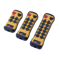
(3) → Scanning 2 channels only (channel X*, channel X*+1)
For Pitch & Catch, Tandem, and Random Access operation with 2 receivers
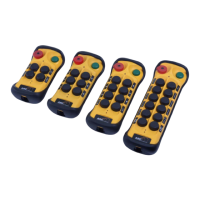
(4) → Scanning 3 channels only (channel X*, channel X*+1, channel X*+2)
For Random Access operation with 3 receivers
* Channel X → Channel set on the receiving module
Example: If the first 6 dip-switch positions on the receiving module is set to Ch.01 (“000000” or
“000001”), when set to 2-channel scanning (type-3 above), then the receiver will only
scan Ch.01 and Ch.02.