16
fig. 1
(A) Key
(B) Outside Lever
(C) Cylinder
(D) Outside chassis
(E) Lever Catch
(F) Latch
(G) Latch/Strike Screws
(H) Strike
(I) Inside chassis
(J) Allen Screw
(A) Mounting Screws
(B) Inside Lever
(M) Cover
(N) Cover Screw
(O) Allen Wrench
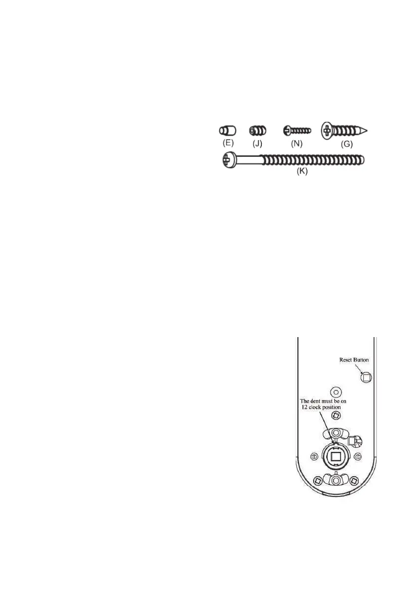
The lock comes with two (K) Mounting
Screws M5x60 2⅜” (60 mm) long, one (N)
M3x25 1”(25 mm) long Cover Screw, one (J)
Allen Screw, one (E) Lever Catch and 4 pieces
(G) Latch/Strike Screws.
Note: The lock fit door thickness between 1⅜” and 2⅜”.
Contact manufacturer to order M5x50 2” (50 mm) long screw if your door thickness is less than 1⅜”.
Tools needed: Phillips Screwdriver, Tape Measure, Pencil, and Flathead Screwdriver.
IMPORTANT NOTES:
• DO NOT use a power drill for installation!
• Install and test lock with door open to avoid being locked out.
1. Install lock on the door.
1.1 The dent should be on 12-clock position (see fig. 1), if not,
rotate Square Spindle to let the dent be on 12-clock position.
1.2 Install the outside chassis unit (see fig. 2). Slide wire through
hole on door. Slide square spindle and poles smoothly through
holes in latch. Take care to keep outside chassis vertically aligned
during installation. Check latch setting and door dimensions if
there is any problem.
1.3 Take care to keep inside chassis vertically aligned during
installation. Connect wire and arrange wire in empty space, take
care to ensure wire is not pinched or crushed at any point during
installation. The Square Spindle slide smoothly into square hole on
Lever Spindle (see fig. 3).
1.4 Insert Mounting Screws to mounting hole on the inside chassis
(see fig. 4), screws should slide smoothly through hole on door.
Use Philip Driver to drive two screws into mounting hole on
mounting poles.