!! ! Installation!Manual!
Page | 10 support@arecontvision.com
!
!
!
+1.818.937.0700 877.CAMERA.8 www.arecontvision.com avsales@arecontvision.com
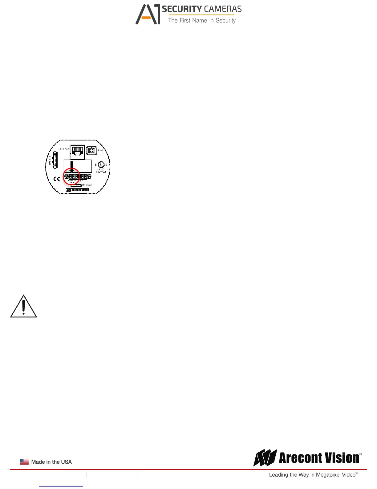
3. If the camera is powered by an outside power supply, connect the power wires to the
appropriate contacts of the 6-postion connector using a small flathead screwdriver and connect
the 6-position plug to the camera as shown in Image 6.
NOTE 1: Ensure that the polarity of the DC input on the camera matches the way that wires are
installed in the connector.
NOTE 2: AC power does not have polarity.
Image 6
Auxiliary Power
If the camera is powered by a separate outside AC or DC power source, run the supplied power cable
through the access hole on the camera housing and connect the power cable to the 2-position
connector on the main camera board. The approximate location of the 2-position connector is circled in
red below.
NOTE: Wiring methods shall be in accordance with the National Electrical Code/NFPA 70/ANSI, and
with all local codes and authorities having jurisdiction. Wiring should be UL Listed and/or Recognized
wire suitable for the application.
For use in ducts, plenums and other air-handling areas, replace Auxiliary Cable provided with CMP,
CL2P or CL3P type wires.
 Loading...