13
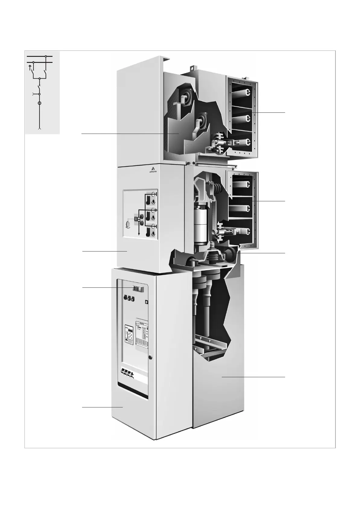
Fig. 3.2
1 Drive with front control panel
2 Tank with circuit breaker
3 Busbar tank 1 with disconnector and earthing switch
4 Busbar tank 2 with disconnector
5 Supporting structure and cable connection
6 Low voltage cabinet
7 Cable test sockets
8 IVIS voltage indicator
3.2 Double busbar panel WSB
1
2
1
8
6
2
4
3
7
5