6.4 Standard switching
operations
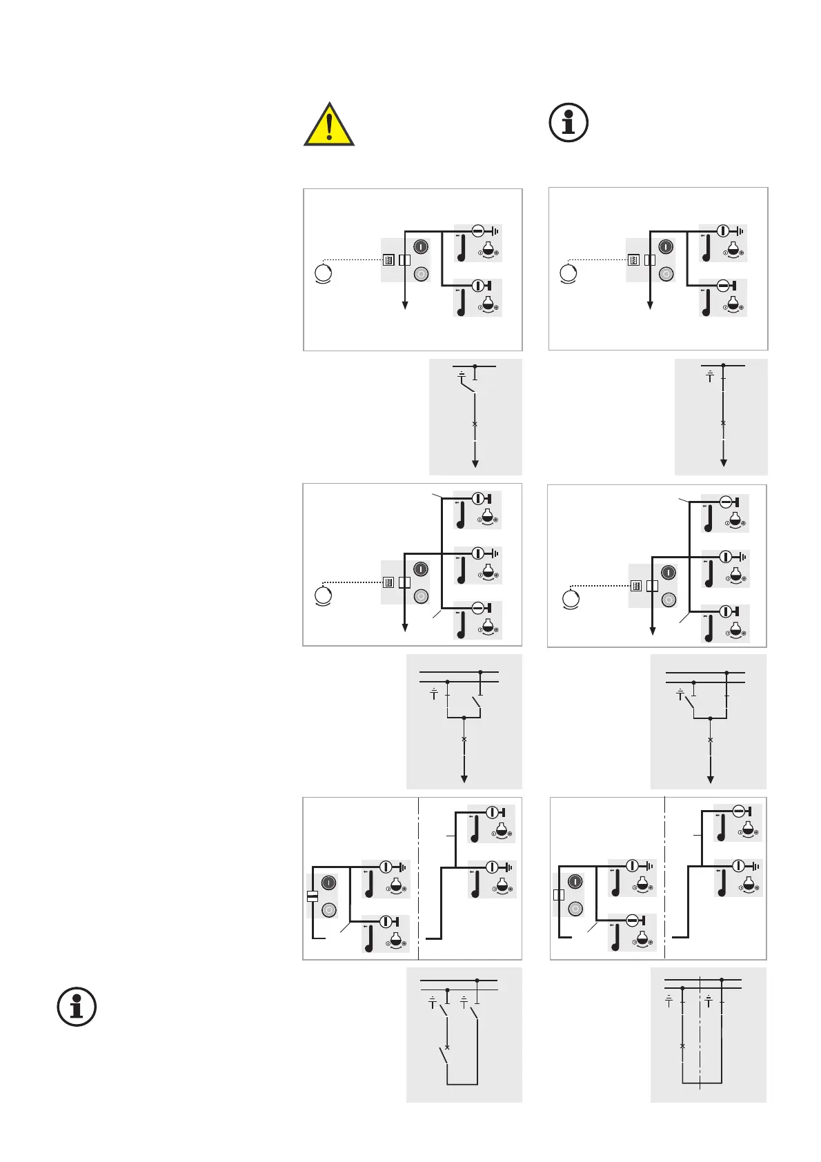
Switching ON an feeder panel
Initial position:
Feeder panel EARTHED
1. Switch earthing switch OFF
2. Switch disconnector ON
3. Switch circuit-breaker ON
Feeder panel ”ON”
Earthing an feeder panel
Initial position: Feeder panel ON
1. Switch circuit-breaker OFF
2. Switch disconnector OFF
3. Switch earthing switch ON
Feeder panel “EARTHED”
Switching over an feeder panel to
the other busbar without interrup-
tion of power supply
(BB = busbar)
Only possible with the bus coupler
switched ON.
Initial position:
Feeder panel on BB1
1. Switch disconnector 2 ON
(Feeder panel on BB1 and BB2)
2. Switch disconnector 1 OFF
(Feeder panel on BB2)
Switching ON a bus coupler
(in two panel widths)
Initial position: bus coupler “OFF“
1. Switch disconnectors 1 and 2 ON
2. Circuit-breaker “ON”
Operating sequence performed in an
analog fashion for bus couplers in one
panel width and bus section coupler.
Important!
When switching off the bus
coupler, at least one dis-
connector must be set to
“OFF” in each feeder panel of the
busbar sections in question.
Warning!
The interlocking con-
ditions acc. to section
5.2 must be complied
with in each case!
Important!
Observe EN 50 110-1
in all switching
operations.
Fig. 6.20
Feeder panel
on BB2
Feeder panel
on BB2
Feeder panel
on BB1