8
2.3 Technical data for
electrical control and
operating devices
The switchgear panels have been
designed on principle for manual
operation.
The drive mechanisms of the indi-
vidual switching devices can be
equipped, depending on the specific
customer's model, with additional
electrical control and operating de -
vices. These are characterized in the
switchgear-specific circuit diagram
(see switchgear documentation).
Component fitting options:
Motor
• for charging the energy-storing
device (closing spring)
• for actuation of the disconnector
and earthing switch
Closing release
• 1 unit
Opening release
• max. 2 units
Secondary release
(CT-powered release)
• max. 2 units
• (Maximum equipment – opening
release and secondary release,
3 units in total)
Undervoltage release
• 1 unit
Blocking coil
Blocking coils prevent the circuit
breaker from being closed and
opened via the mechanical push-
buttons “ON“ or “OFF“, as well as
actuation of the interlocking levers of
the disconnectors and earthing swit-
ches.
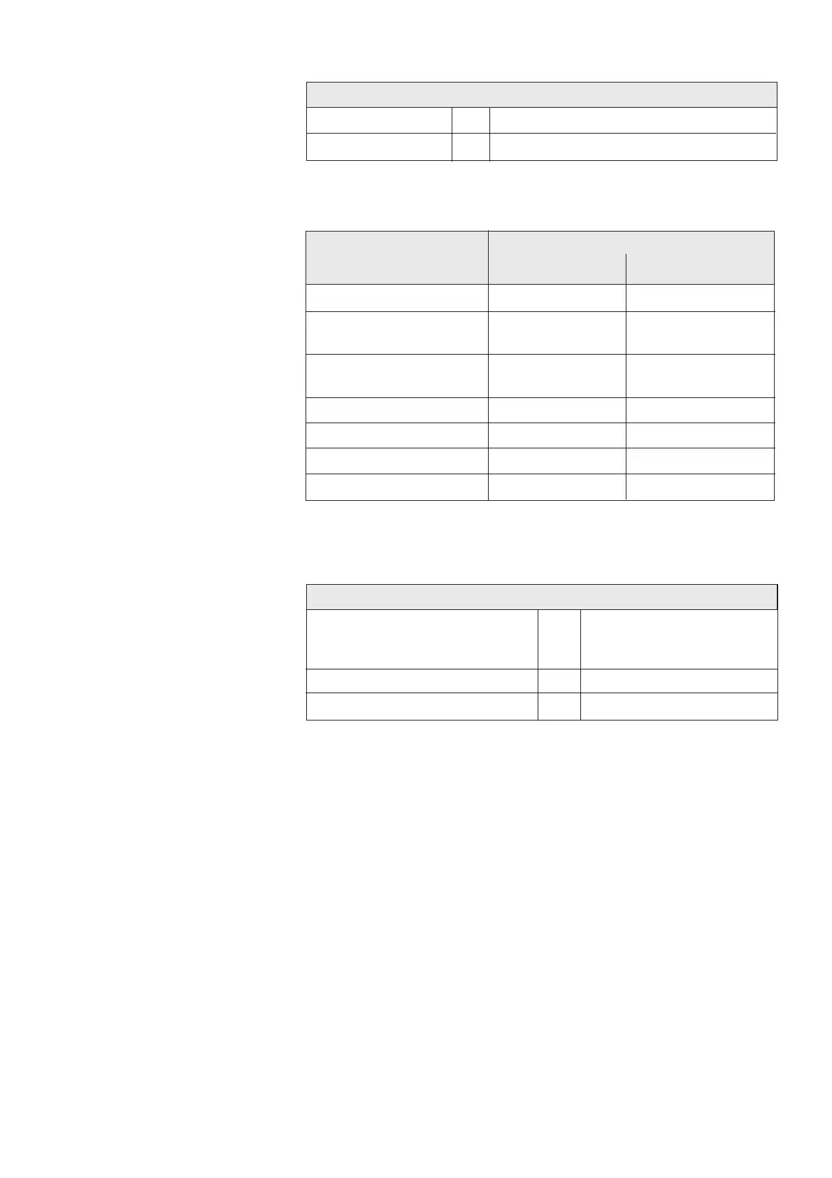
Times for releases and motor
Minimum tripping command duration
for release 160 W [ms] 20
for release 25 W [ms] 50
minimum closing command duration [ms] 20
Motor charging time [s] ≤ 12
Overview rated supply voltages
DC voltage: [V] 24 / 48 / 60 / 110 / 125 / 220
AC voltage: [V] (110) 120 / (220) / 230
Power consumption, solenoids and motor
Power consumption
DC AC 50/60 Hz
approx. [W] approx. [VA]
Closing release 160 160
Opening release without
auxiliary spring energy store 160 160
Opening release with
auxiliary spring energy store 25 25
Undervoltage release 15 15
CT-powered release – 12
Blocking coil 12 12
Motor 200 - 250 200 - 250
Please enquire at the manufacturer’s for details of the motor’s starting current.
The auxiliary voltage data is required to this effect.