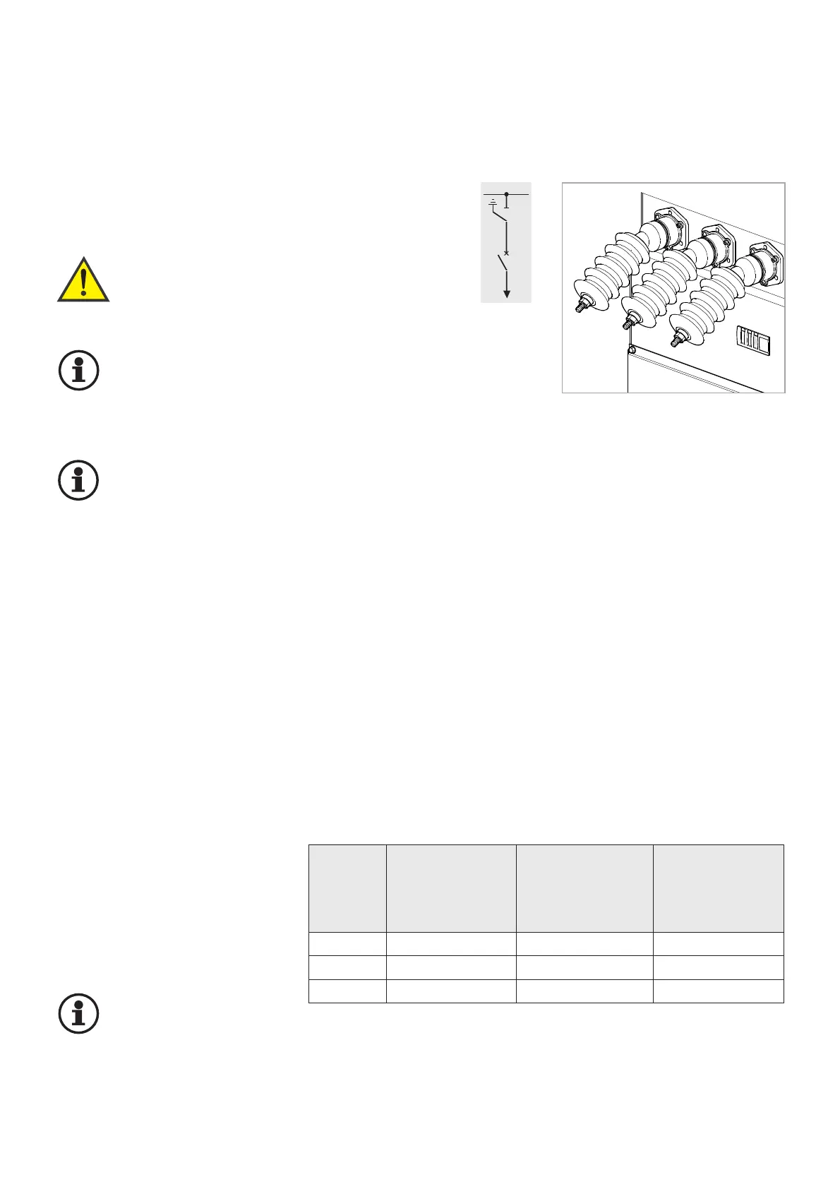
Perform cable tests on the rear test
sockets (see Fig. 8.1).
Warning!
Comply with the safety
provisions in section
1.5!
Important!
The busbar can be operated
with rated voltage during
cable tests in the feeder
panel (see rating plate).
Important!
Observe the assembly and
test instructions for the
cable fittings and the termi-
nating connectors!
1. Isolate feeder panel cable of the
appropriate switchgear panel.
2. Isolate feeder panel cable in
remote station.
3. Earth feeder panel cable.
4. Disconnect the following devices,
earth them if envisaged:
- pluggable voltage transformers;
- pluggable surge arresters;
- measuring amplifiers for capa-
citive voltage measurement.
If non-detachable voltage transfor-
mers (connected via cable) are
used, these must be disconnec-
ted on the switchgear end and the
sockets must be closed “voltage-
proof” using dummy plugs.
5. Remove test socket dummy
plugs.
6. Connect the test adapter/test
cable to test sockets and test unit
(observe the manufacturer’s
instructions).
Important!
Make sure that the distance
between the metallic com-
ponents of the test set-up
and the earthed switchgear suppor-
ting structure is sufficiently dimen-
sioned.
7. Switchgear panel in
test position:
In case of the inter-
tripping circuit, the
circuit-breaker is
switched off by actu-
ation of the earthing
switch towards “OFF”:
Turn interrogating lever “earthing
switch” and insert the crank. Turn
crank counter- clockwise by
approx. 1 turn, until the circuit-
breaker has switched off.
The test position is reached.
8. Perform cable check observing
the instructions of the cable or
cable connector manufacturer.
Once the cable test has been
completed:
9. Earth feeder panel cable again:
- Turn earthing switch
completely OFF;
- charge the energy-storing
device;
- turn earthing switch ON again.
10. Re-connect the disconnected
devices.
11. Remove test set and close test
socket “voltage-proof” using the
dummy plug.
Cable test from the opposite end
with the cables connected, on the
WS switchgear:
For test set-up and implementation,
refer to the instructions of the cable
manufacturer.
Refer to items 1-4 an 7-10 of this
section!
31
U
0
/U (U
m
) Test DC voltage 0.1 Hz 45 - 65 Hz
1)
Initial / repeat power-frequency power-frequency
test test voltage test voltage
[kV] [kV] [kV] [kV]
max. 15 min. max. 30 min. max. 30 min.
6/10 (12) 48/34 18
2)
12
2)
12/20 (24) 96/67 36
2)
24
2)
18/30 (36) 108/76 54
2)
36
2)
1)
Description U
0
/U (U
m
): HD 620/621 S1 or IEC 60502-2
2)
Repeat tests with alternating voltage:
performed with 80 % of the values specified in the Table.
Admissible limits for the switchgear in case of cable tests:
8 Cable test
>>
Fig. 8.1
High-voltage cable test via rear-side
test adapters