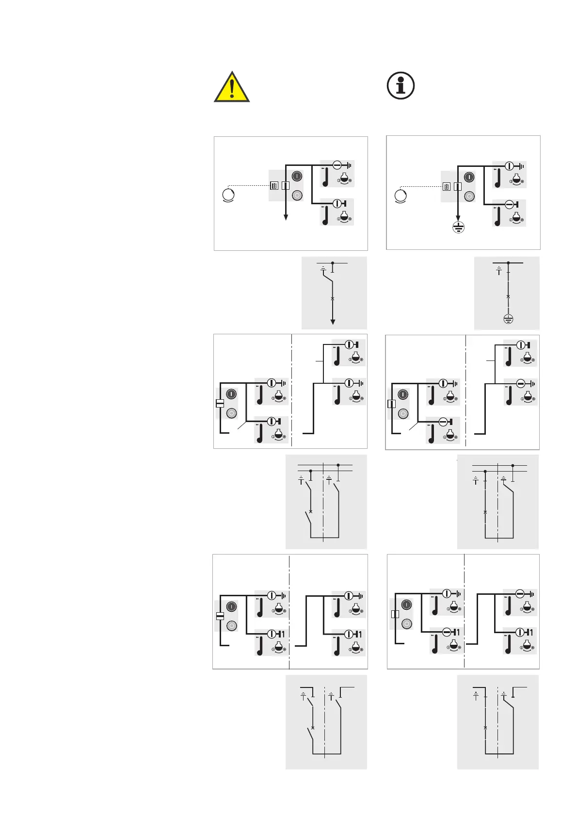
Earthing a busbar section by
means of the bus section coupler
Illustrated: Earthing the left-hand
busbar section
Initial position:
Bus section coupler "OFF"
1. Switch on disconnector of left-
hand busbar section (circuit-
breaker panel)
2. Switch on earthing switch in the
busbar riser panel (right-hand
panel)
For earthing the right-hand busbar
section, proceed analogously.
Earthing a busbar section by
means of the bus coupler
(BB = busbar)
Illustrated: Earthing of BB1
(lower busbar).
Initial position: bus coupler “OFF“
1. Switch disconnector of the BB1
(circuit-breaker panel) ON
2. Switch earthing switch in the
busbar riser panel
(right-hand panel) ON
For earthing BB2 (upper busbar),
proceed analogously.
27
Earthing the busbar by means of
a feeder panel via its circuit-
breaker
Initial position:
Feeder panel EARTHED
1. Remove cable and connect eart-
hing device (optional).
Alternatively, the earthing device
can be connected to the cable
test sockets, if I
k
≤ 31.5 kA / 1s.
2. Switch earthing switch OFF
3. Switch disconnector ON
4. Switch circuit-breaker ON
6.5 Earthing the busbar Warning!
The disconnectors
on the appropriate
busbar sections
must be “OFF”!
Important!
Comply with EN 50 110-1
in all switching
operations.