10
TEMPERATURE CONTROL RANGES:
Temperature: Degrees Fahrenheit
Operating Temperature Range:
90°F - 180°F
(Factory Setting: 180°F)
Operating Temperature Differential Range:
+/- 4°F - +/- 20°F
(Factory Setting: 12°F)
Fixed High Limit Temperature: 200°F
OPERATING TEMPERATURE AND DIFFEREN-
TIAL ADJUSTMENTS: Internal temperature poten-
tiometer on the control.
CONTROL OPERATION: When the control switch
is in the "On" position and all safety end switches
are closed, the "Safety Switch" LED is lit. Once in
operating mode, the control uses the well-mounted
(RTD) sensor to continuously monitor the boiler
water temperature.
When the thermostat calls for heat ("TT" LED is lit),
the control will energize the circulator ("Circ" LED
is lit) for 30 seconds to establish ow. Next the con-
trol will measure water temperature and differential
setting, perform a check for an "open" or "shorted"
RTD sensor, check that all safety end switches are
"closed," and check for stuck or welded element
relay contacts. Next, the control will energize only
one element ("Element" LED is lit) and monitor
water temperature for 60 seconds. The control will
energize additional elements at 30 second intervals
to bring the system up to set point temperature in
5 minutes.
Once the system reaches the set point temperature
and there is still a call for heat, the control will modu-
late the number of elements on and off in order to
maintain the set point temperature. The required
number of elements which are energized is deter-
mined by heating demand, which is the difference
between actual boiler water temperature and set
point temperature.
After the call for heat has been satised, the elements
will be de-energized ("Element" LEDs turn off) by
the control and the circulator will continue to be
energized for 3 minutes to purge the boiler. After
3 minutes the control will de-energize the circulator
("Circ" LED turns off).
If at any time during the start-up of the boiler or during
operation a safety end switch opens its respective
contact, the control de-energizes all elements,
continues to energize the circulator, and ashes a
visible fault code ("Fault" LED ashes) along with
an audible fault code. (See fault codes (below)) The
control has a built-in reset function.
TEMPERATURE SETTING: The water "Set
point" temperature adjustment dial on the control
should always be set at the designed boiler water
temperature.
CONTROL MOUNTING: The control is mounted
using 1/2" tall plastic standoffs. The indicator LEDs
are visible through a clear polycarbonate viewing
window on front cover of the boiler.
PROTECTION FROM LIQUIDS: The control and
other components located within the control panel
are sensitive to water and other liquids. Measures
must be taken to fully protect components on panel
from contact with liquids.
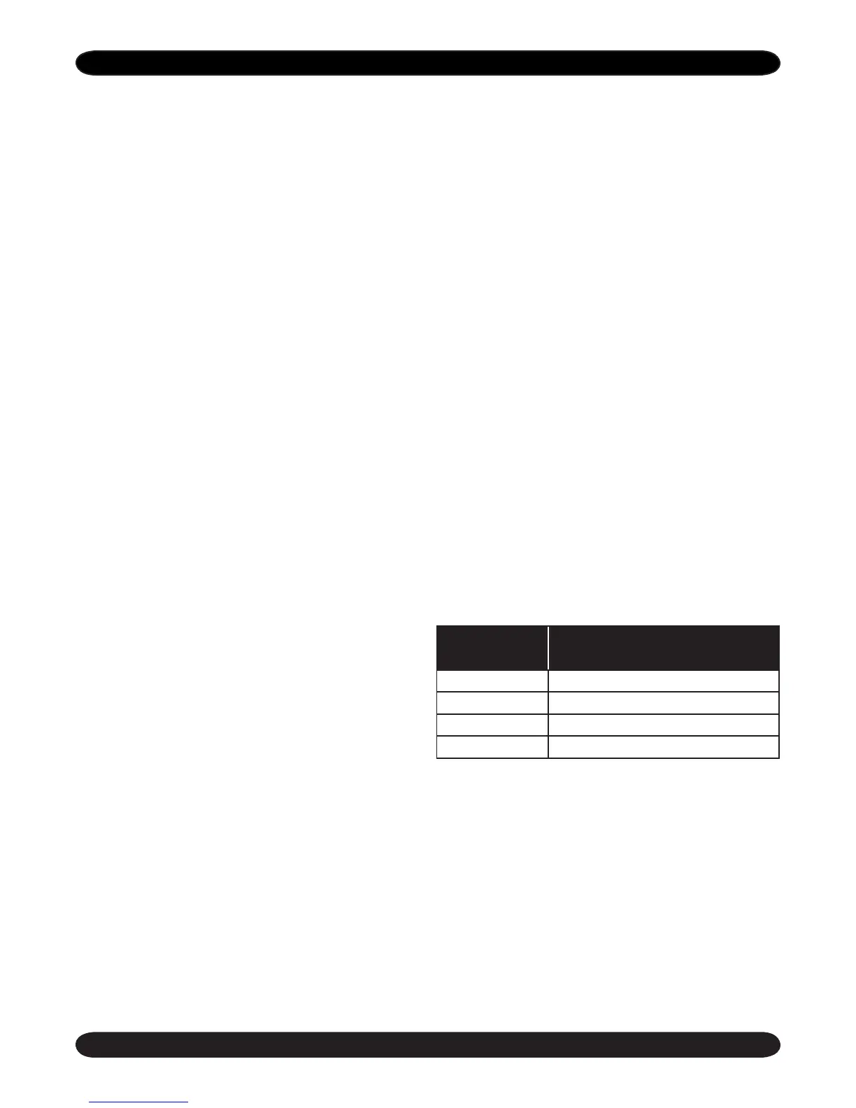
FAULT CODES (VISUAL/AUDIBLE):
RTD SENSOR:
To conrm that the RTD sensor is functioning prop-
erly, follow the steps below.
1. Remove both RTD leads from the terminal block
on the boiler control board.
2. Use a multimeter to take an ohm reading across
the RTD leads. A properly functioning RTD will
produce a reading of approximately 1000 ohms
at 70° F. A faulty RTD will read either 0 or 1 on
your multimeter.
3. Replace RTD if necessary.
Number of
Flashes/Pulses
Description
1 Safety switch fault
2 Stuck/welded element relay contact
3 RTD short
4 RTD open
CONTROL INFORMATION
continued

 Loading...