8
CONNECTING ELECTRICAL POWER SUPPLY
! !
WIRING THE BOILER
WARNING
DO NOT USE ALUMINUM WIRE!!
Argo Electric Hydronic Boilers are pre-wired for
use with 240-volt, 3 wire, single-phase, 50/60-hertz
power. Refer to Table 1B on page 4 for the reduction
in boiler capacity when the line voltage is less than
240 volts.
An opening is provided in the jacket bottom panel
for the eld wiring, refer to the rating chart for
recommended wire sizes.
All electrical wiring must be done in accordance with
the Canadian Electrical Code, CSA C22.1 Part 1, and
/or any local regulations and codes in Canada, or
the National Electrical code, ANSI/NFPA 70 (Latest
edition) and/or any local regulations and codes in
USA. Verify the nameplate rating and check the
related codes to properly size conductors, switches
and over current protection. Several openings are
provided on the bottom of the cabinet for different
voltage connections. For wire connections refer to
the wiring diagram on the inside of the boiler front
cover. Do not use aluminum wire!!
All circuit breakers or disconnects ahead of the boiler
must be OFF. If boiler contains integral breakers
(depending on option), it is recommended that they
are also turned off at this time. Remove the boiler front
cover by removing 4 screws from the top and sides.
When a boiler is used in a zoned system, the zone
valves must be powered from an independent
source and have electrically isolated end switches
or isolating relays wired in parallel to the boiler
thermostat terminals. Do not attempt to power
zone valves from the transformer in the boiler
control system!!
WIRING ON CONTROL
PUMP: Connect only 120 Vac 1/6 HP (maximum)
pump to terminals C1(L) and C2(N) on the controller.
Strip wire ends before inserting into terminal block.
Tighten terminal screws. Do not use a pump
requiring greater than 5 amps!!
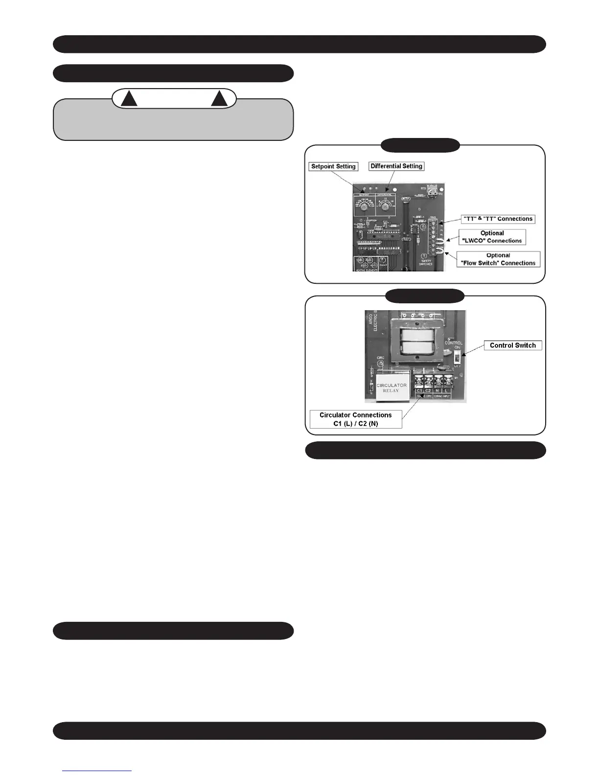
THERMOSTAT: Connect thermostat or zone valve
end switch to terminals TT and TT (Figure 4). Do
not apply an external power source to these
terminals!! Strip wire ends before inserting into
terminal block. Tighten terminal screw clamps.
LIMIT CONTROL OPERATION
1. When the boiler water temperature exceeds the
high limit setting on the aquastat, all heating
element control relays are instantly de- energized.
Circulator continues to operate until call for heat
ends. When water temperature drops below
aquastat re-set differential, heating element power
relays close as per time delay sequence.
2. MAIN POWER SUPPLY: Depending on model
designation, the electric Hydronic Block may be
energized by the following alternating current
service entrances: 240 volt single phase 50 or
60 cycle 3 wire. The wire size required may be
selected from Table 1. The sizes listed for various
capacity units include total amperes necessary
to operate elements, circulator and zone valves
where used. Wire sizes specied conform to the
Canadian Electrical Code (Canada) or National
Electric Code (USA) and include derating for
FIGURE 4
FIGURE 5

 Loading...