6
DESIGN OF WATER
CIRCULATING SYSTEM
System should be designed as primary/secondary
piping and to operate with a maximum output tem-
perature of 180º F or lower and a temperature rise
across the unit of 20º F or lower. Refer to tables
below and Figures 2 & 3.
NOTE: To prevent condensation, the return water
temperature must be higher than the room tem-
perature in which the boiler is installed.
at the bottom of the unit. Reverse ow will result
in a noisy operation and cause very early element
failure. The drain cock is to be located at the
lowest point of piping.
5. The outlet or supply pipe line to the radiation
is located at the top of unit. A combination
temperature pressure (altitude) gauge is provided
with each unit and should be installed close to the
boiler outlet. It is important that the gauge sensor
be completely immersed in the owing water so as
to assure correct temperature readings. Manual or
automatic water make up supply may be located
in this area below. The circulator pump should be
installed on the supply side (pumping away).
6. Gate valves should be installed at the locations
shown in Figures 2 & 3, so that any boiler servicing
requiring removal of water can be done quickly and
easily. Not illustrated but also highly recommended
is the installation of air vents at the high points
of the hydonic system. These devices will reduce
initial start up time and help avoid element burnout
during the entire life of the heating system.
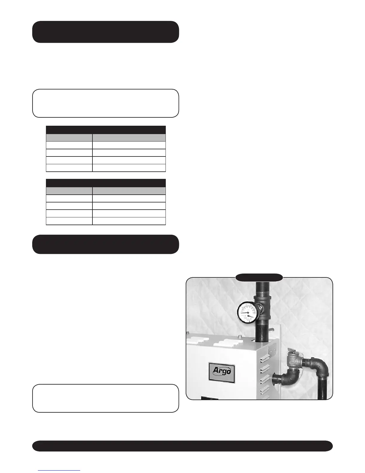
7. A pressure relief valve is supplied with each
Electric Hydronic Block and should be installed
at the location and discharge direction shown in
Figure 1, using pipe nipple and elbow supplied.
Piping should be added so that any water that
may be discharged will not damage the boiler or
other system components.
PLUMBING AND
ACCESSORY
INSTALLATION
FIGURE 1
8. For further piping information refer to The Hydronics
Institute (I=B=R) manual 200 (Installation Guide for
Residential Hydronics).
“AT” Series - 2 Element Boiler
KW Capacity Minimum Flow Rate (GPM)*
6 2.0
8 2.7
10 3.4
12 4.1
“AT” Series - 4 Element Boiler
KW Capacity Minimum Flow Rate (GPM)*
12 4.1
16 5.5
20 6.8
24 8.2
* Flow rate based on 20°ΔT
CONNECTING SUPPLY
AND RETURN PIPING
1. Maintain a minimum clearance of one inch to hot
water pipes.
2. Hot water boilers installed above radiation level
must be provided with a low water cutoff device
either as part of the boiler or at the time of boiler
installation.
NOTE: In some states a low water cutoff device
(LWCO) may be required. Check your local codes.
3. When a boiler is connected to a heating system
that utilizes multiple zoned circulators, each
circulator must be supplied with a ow control
valve to prevent gravity circulation.
NOTE: Reduced pressure back ow provender
must be present under provisions required by the
Environmental Protection Agency, (EPA).
4. Suggested plumbing arrangements are illustrated
in Figures 2 & 3. The inlet or return pipe is located
 Loading...