V 10/19
80
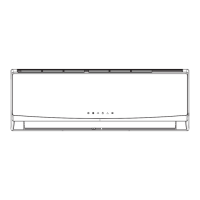
Step seven: connect the indoor unit electrical cable
1. Open the panel. Remove the screw that
secures the small panel covering the terminal
board.
2. Insert the indoor and outdoor unit connecting
cable into the rear hole corresponding to the
terminal block. Then pull it out of the front.
pannello panel
vite screw
coperchio cablaggio wiring cover
foro di passaggio cable
cavo through-hole
cavo di alimentazione power cable
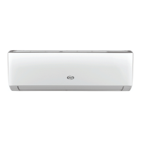
6. Remove the cable clip. Connect the power cable to the terminal block according to colour. Tighten
the screw and secure the power cable with the clip.
blu blue
nero black
marrone brown
giallo-verde yellow-green
collegamento unità esterna Outdoor unit connection
4. Reposition the terminal block cover and tighten the screws.
5. Close the panel.
N.B.:
• All wiring must be connected as shown on the unit's wiring diagram.
All indoor and outdoor unit cables must be connected by a qualified technician.
• If the power cable is not long enough, contact the supplier for a new one. Do not attempt to extend
it yourself.
• For air conditioners equipped with a plug, the plug must be easily accessible upon completion of
installation.
• For air conditioners without a plug, install a circuit breaker on the line. The circuit breaker must
be single-pole and the contact gap must be greater than 3mm.
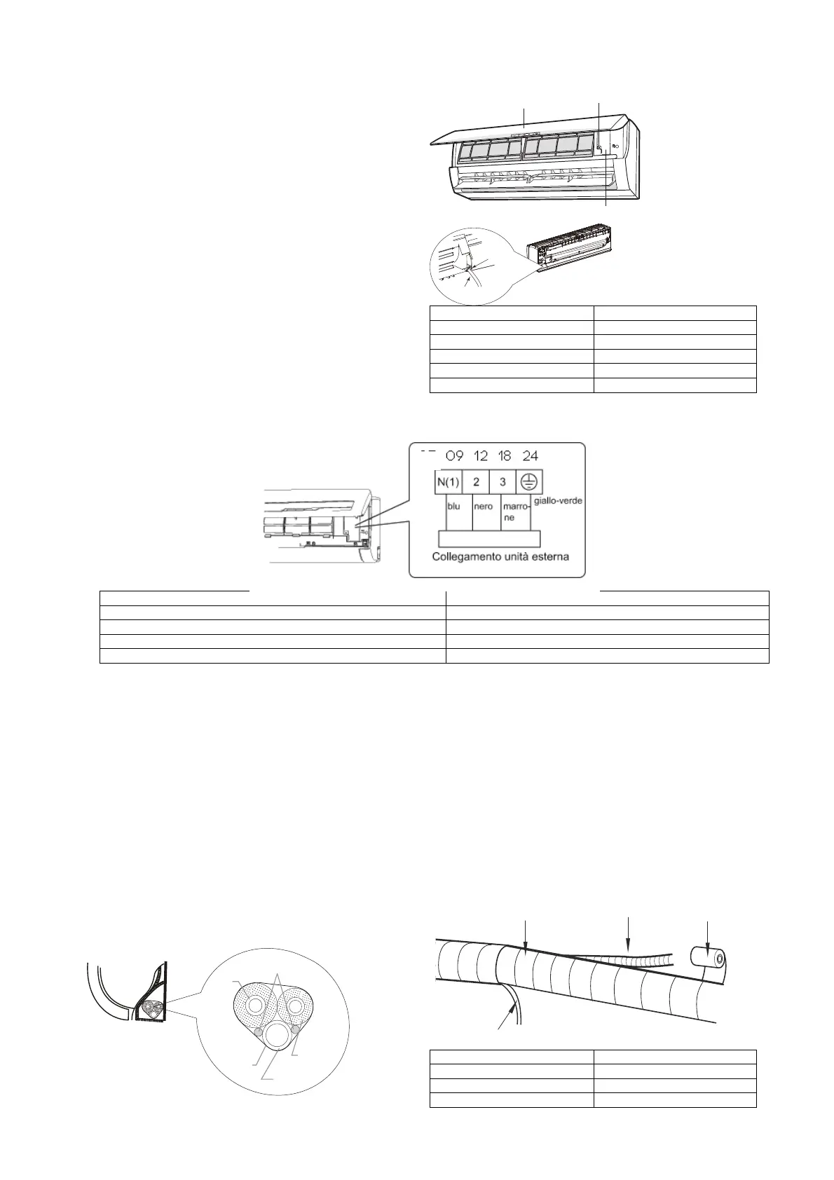
Step eight: bind the pipes
1. Bind together the connecting pipe, the power
cable and the drain pipe with binding tape.
tubo di collegamento connecting pipe
tubo di scarico drain pipe
fascetta binding tape
cavo di alimentazione interno Indoor powercable
coperchio cablaggio
vite
pannello
cavo di
alimentazione
foro di
passaggio
cavo
unità
interna
tubo
gas
cavo di alimentazione
interno ed esterno
tubo del
liquido
tubo di
scarico
fascetta
tubo di scarico
tubo di collegamento
cavo di alimentazione interno
fascetta
 Loading...