FOR MODELS: JGI, JGM, JGN, JGP AND JGQ SECTION 2 - INSTALLATION
9/08 PAGE 2-7
the crankshaft.
•
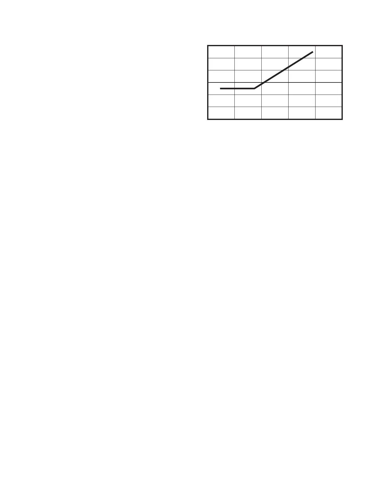
0
0.012
0.010
0.008
0.006
0.004
0.002
0.000
10 20 30 40 50
Hub Diameter, in.
Angular TIR Limit, in.
FIGURE 2-3 ANGULAR COUPLING-HUB
A
LIGNMENT TIR LIMITS
To ensure parallel and concentric
drive train alignment, position
connected equipment so total
indicator (TIR) is as close to zero
as possible on the coupling hub
faces and rim diameters at nor-
mal operating temperature. Do
not exceed 0.005 inches
(0.13 mm) on the face and rim
diameter. Except for coupling
hubs with outside diameters
above 17 in. (43 cm), the angular
face TIR limit is 0° 1’ or 0.0167°.
See Figure 2-3. Correct for “Cold
Alignment” on page 2-10.
Hub O.D. >17 in. x 0.00029 = angular TIR, in. max.
Hub O.D. >43 cm x 0.0029 = angular TIR, mm max.
• Center the coupling between the driver and the compressor so that it does not thrust
or force the crankshaft against either thrust face.