EN - 14
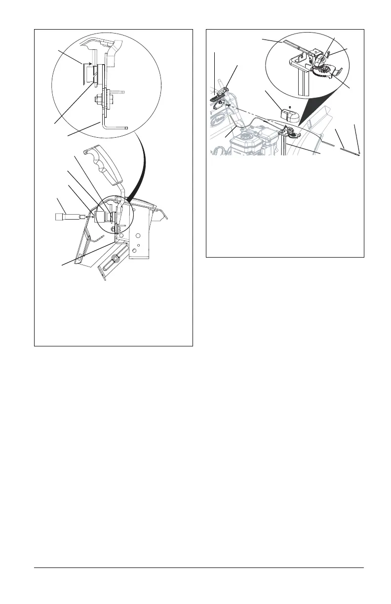
NOTICE: To ensure the discharge chute
follows its full range of travel, make sure the
control lever is centered in the slot and
pointing straight up before installing the chute
rod.
9. Insert chute rod end without ears into
control lever and slide into control p
anel
unt
il opposite end of rod clears the
gear
ass
embly.
10. Align end of chute rod with hex hole
in
gear ass
embly and insert until ears hit
gear.
11. Insert hairpin into hole in chute rod
near
gear ass
embly.
12. Hook the chute control cable onto t
he
chut
e rod.
IMPORTANT: The chute control cable hook
will prevent the cable from contacting the
engine or muffler guard. Make sure this cable
stays connected while unit is in operation.
13. Check to make sure the chute cont
rol
cable ends are
properly seated in control
assembly and lock arm.
14. Adjust control cable as necessary to
remove cable slack. Be sure lock arm is
fully seated in gear teeth.
15. Replace gear cover on top of chut
e
pedes
tal.
Figure 13
1. Control Assembly
2. Nylon Bushing
3. Push Nut
4. Socket Extension (Optional)
5. Socket, 3/4"
1
1
2
3
2
3
4
5
Figure 14
3
1. Chute Rod
2. Gear Cover
3. Control Assembly
4. Gear Assembly
5. Chute Control Cable
6. Alignment Marker
7. Chute Pedestal
8. Rubber Grommet
9. Hair Pin
2
1
9
4
5
6
8
7
1
9
 Loading...