8 Ariens® 932 Sno-Thro® Orig. 6/99
Hardware/
Literature
Pack
The pinion bracket that is secured to chute strap is
slotted for adjustment (Figure 4). Adjust so that pinion
and flat gear mesh together smoothly.
The chute bracket and gear strap are also slotted for
vertical adjustment of the discharge chute (Figure 4).
Loosen mounting nut and move discharge chute up or
down so that chute ring is approximately centered
between retainer clip and lower ring. Then tighten.
3. Discharge Chute Crank
Place discharge chute crank rod through bracket on the
handlebar panel and into pinion on discharge chute
assembly and secure with hair pin. Install the gear
cover.
4. Connect Attachment Clutch
Hook control cable spring in frame back anchor then
slide cable housing into slot on the attachment clutch
arm (Figure 5). Adjust per Maintenance Section.
5. Connect Traction Drive Clutch
Place the Z bend end into the traction drive clutch lever
and the cable eyelet end on the small hook end of the
traction drive link (Figure 5). Then hook the link to the
traction drive clutch arm. Adjust per Maintenance
Section.
WARNING
FAILURE TO FOLLOW INSTRUCTIONS could result in
personal injury and/or damage to unit. Read, understand,
and follow all safety practices in Owner/Operator Manual
before beginning.
ACCIDENTAL ENGINE START UP can cause death or
serious injury. ALWAYS remove key and/or wire from spark
plug before assembly.
Tools Required:
• Open-End Wrenches and/or Adjustable Wrench
• Tire Gauge
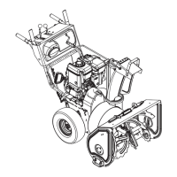
Package Contents:
Sno-Thro
Assembly
Discharge Chute Assembly
Handlebar
Assembly
DS0141
ASSEMBLY CHECKLIST
Check each box after completion.
1. Install Handlebar
Attach handlebars to sides of frame in holes provided
using 5/8” long flange whizlock screws.
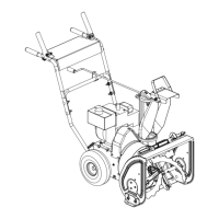
2. Install Discharge Chute
Remove mounting hardware from on top of engine, near
spark plug (Figure 3). Position discharge chute over
opening on auger/impeller housing under retainer clip
and secure by fastening chute strap to engine with
hardware just removed. Lock washers go on top of
chute strap.
Crank
Assembly
1. Mounting Hardware
2. Discharge Chute Crank
3. Chute Strap
4. Discharge Chute Bracket
5. Gear Cover
Figure 3
DS0122
1
2
5
3
4
SECTION 3: ASSEMBLY

 Loading...