23
installationinstallazione
N
N
FLAME
L
L
BUS
TB
FLOOR
TA2
SE TNK SOL TA1
CN14
CN13
CN19
CN1
CN2
CN11
CN4
1
1
1
CN8
CN25
1
BUS
TB
TA2
FLOOR
SE TNK SOL TA1
CN1
1
Collegamenti AT
HV Connection
Bk
Bk
Gr
Wh
Rd
Bl
Circolatore modulante
Modulating circulation pump
Circolatore modulante
Modulating circulation pump
Ventilatore modulante
Modulating fan
Elettrodo rilevazione amma
Detection electrode
Collegamenti BT
LV Connection
CN6
N
N
FLAME
FUSE
L
L
CN19
CN1
CN2
CN11
CN4
1
1
1
1
Bk
Bl
Br
1
1
CN9
1
1
1
1
CN6
Periferiche
Peripheral unit
Collegamenti BT
LV connections
Collegamenti AT
HV connections
Collegamento Periferiche
Peripheral unit connection
Controllo Remoto
Remote Control
Sonda Esterna
Outdoor sensor
Termostato Ambiente1
Room Thermostat 1
OK
Sensys
1234567
Valvola gas
Gas valve
Accenditore
Spark generator
Bk
Bk
Br
Bl
Valvola deviatrice
motorizzata
Diverter valve
Bk
Bk
CN14
CN13
1
1
CN8
CN9
1
1
CN25
1
Display
Flussostato sanitario
D.H.W. ow switch
GENUS PREMIUM EVO
Sensore di pressione
Water pressure sensor
Br
Rd
Rd
Bl
Bl
Br
Br
Bk
Bk
Bk
Bl
1
CN6
Bk
Br
Sonda ritorno risc.
C.H. Return temp. probe
Sonda mandata risc.
C.H. Flow temp. probe
Termofusibile
Thermal fuse
11
1
1
CN6
CN11
Sonda bollitore
Tank sensor
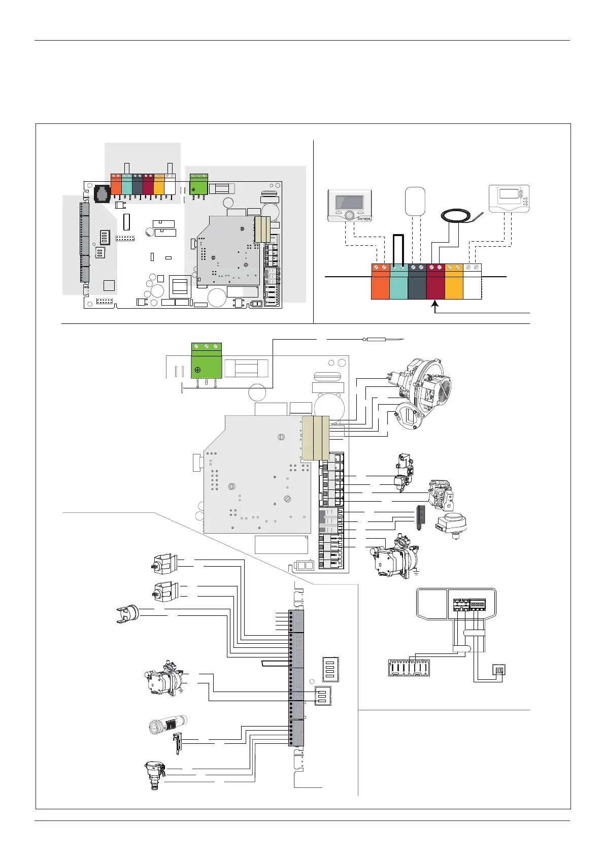
GENUS PREMIUM EVO SYSTEM
Schema elettrico caldaia
Per una maggiore sicurezza far e ettuare da personale quali cato un
controllo accurato dell’impianto elettrico.
Il costruttore non è responsabile per eventuali danni causati
dalla mancanza di messa a terra dell’impianto o per anomalie di
alimentazione elettrica.
GENUS PREMIUM EVO
Bk= Nero - Black
Rd = Rosso - Red
Gr = Verde - Green
Bl = Blu - Blue
Br = Marrone - Brown
Wh = Bianco - White
Gry = Grigio - Grey
Electrical diagram
For increased safety, ask a quali ed technician to perform a thorough
check of the electrical system.
The manufacturer is not responsible for any damage caused by the
lack of a suitable earthing system or by the malfunctioning of the
electricity mains supply.
 Loading...