15
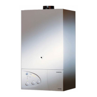
Technical Data Capacity Coil C.H.W. D.H.W. Max Heating Heat Ioss
Surface Flow/rate Flow/rate Output
MODEL It. m
2
m
3
/h It/h kW kWh/24h
Contract STI 125 Indirect 125 0.75 0.5 194 11.3 2
1 266 15.5
2 340 19.8
Comfort STI 125 Indirect 125 0.75 0.5 256 14.9 2.2
Contract STI 150 Indirect 150 0.93 1 353 20.5
2 451 26.2
Comfort STI 150 Indirect 150 0.93 0.5 256 14.9 2.4
Contract STI 210 indirect 200 0.93 1 353 20.5
2
451 26.2
Comfort STI 210 Indirect 200 0.93 0.5 256 14.9 2.9
Contract STI 300 Indirect
300 0.93 1 353 20.5
2 451 26.2
SB 125 Indirect 125 1 0.5 190 11 1.72
1 318 18.5
2 496 28.8
SB 150 Indirect 150 1 0.5 190 11 1.75
1 318 18.5
2 496 28.8
SB 200 Indirect 200 1.3 0.5 190 11 2.1
1 318 18.5
2 496 28.8
TABLE 3.1
MTS support the initiative. Within the information pack you will find a copy
of the Log Book.
It is impor
tant that this is completed in the presence of y
our
customer, they are shown how to use it, and it is signed by them. Please instruct your
customer that they must have their Log Book with them whenever they
contact a service engineer or us.
Preliminar
y electrical system checks to ensure electrical safety must be carried out
by a competent person i.e. polarity, earth continuity, resistance to earth and short
circuit.
FILLING THE HEATING SYSTEM:
Remove the panels of the case and lower the control panel (see section 3.3 for
further information).
Open the central heating flow and return cocks supplied with the connection kit
(there are two isolation points on the return connection).
Unscrew the cap on the automatic air release valve one full turn and leave open
permanently.
Close all air release valves on the central heating system.
Gradually open valve(s) at the filling point (filling-loop) connection to the central
4. COMMISSIONING
4.1 INITIAL PREPARATION
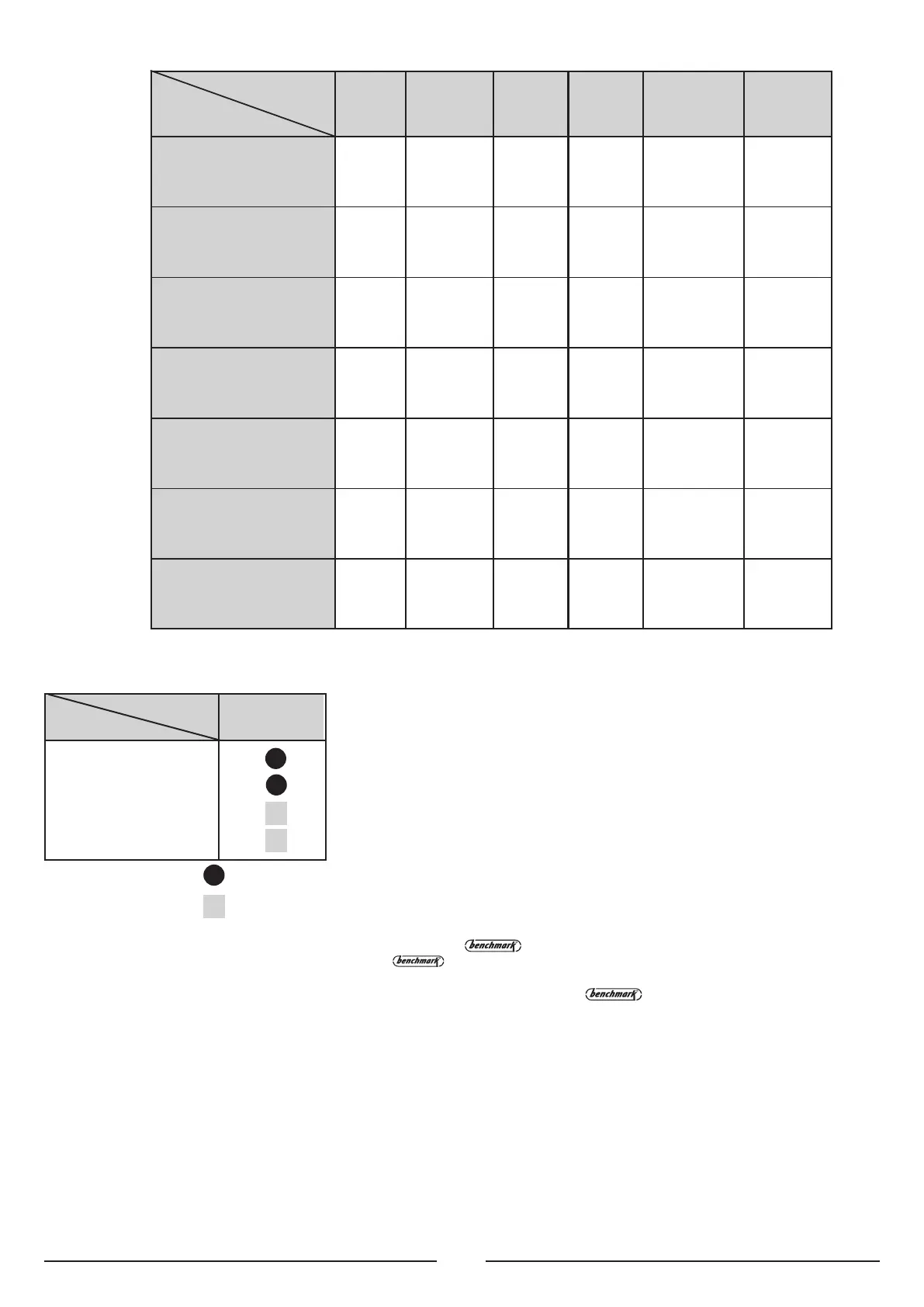
Boiler microSYSTEM
15 RFFI
Cylinder
= Ideal
= Possible
The microSYSTEM is able to be connected to a specially designed kit for the
management of D.H.W. production. This kit gives priority to production of D.H.W. unlike
traditional systems where the boiler power is split between C.H. and D.H.W. This
generally enables a smaller storage cylinder to be chosen as the boiler’s full output
will be channelled into the cylinder allowing for a quick heat-up.
The kit (ARISTON part number 706329) can be obtained from an ARISTON supplier.
The kit consits of:
1) Electronic module able to plug into the boiler’s P.C.B;
2) 3-way priority valve with actuator for connection to the boiler’s flow outlet;
3) A limit thermostat (80˚C) to check the water temperature of the heating flow to the
cylinder, to be installed within the boiler;
4)
Pipes and accessories.
Contract STI 125 Indirect
Comfort STI 125 Indirect
Contract STI 150 Indirect
Comfort STI 150 Indirect
TABLE 3.2
3.2 DOMESTIC HOT WATER
PRIORITY KIT
 Loading...