11
T
o connect a room thermostat and/or time clock, it is necessary
to:
1. - Open the control panel as indicated in section 4.3;
2.-
Remove screws
“A” and remo
ve the inspection cover from
the reverse of the control panel;
3.
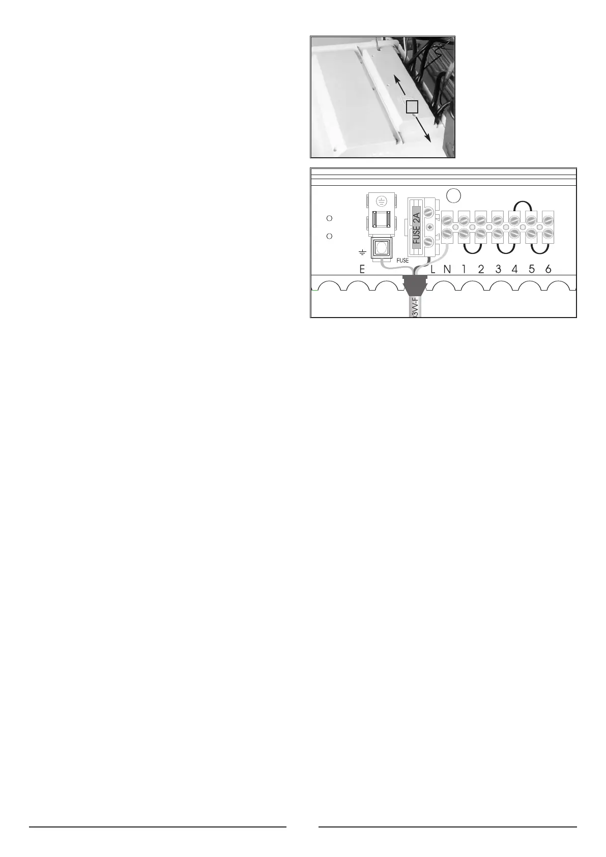
- For the room-thermostat connect the thermostat switching
wires to the position 5 and 6 and remove the wire link (for
three-wire thermostats connect the neutral to terminal
N);
4. - For the time clock connect the clock switching wires to the
positions 3 and 4 and connect the clock motor electrical
supply to the terminals marked
L and N.
Note:
A frost thermostat is built-in to the appliance.
For connection to control systems with zone valves
for hot water cylinders see section 3.
2.11 ROOM THERMOSTAT
CONNECTION
A
2.12 ELECTRICAL DIAGRAM
Legend: A - On/Off Switch
B - On/Off L.E.D.
C - Heating Switch
D - Heating L.E.D.
E - Reset Button
F - Ignition Failure (Lockout) L.E.D.
A01 - Pump Pressure Switch
A02
-
F
rost Thermostat
A03
- Modulator
A04 - Circulation Pump
A05 - Regulation Thermostat
A06
-
Exter
nal Control System
A07
- Time Clock Connector
A08 - External (Room) Thermostat
A09 - Air Pressure Switch
A10 - Fan
A11
- Overheat Thermostat
A12 - Spark Generator/Gas Valve Supply
A13 - Detection Electrode
Colours:
Wh
- White
Bl - Blue
Gry - Grey
Brn - Brown
Blk - Black
Rd - Red
Grn/Yll - Yellow/Green
 Loading...