L =
Sum of the total length of e
xhaust + air
intake piping.
Exhaust
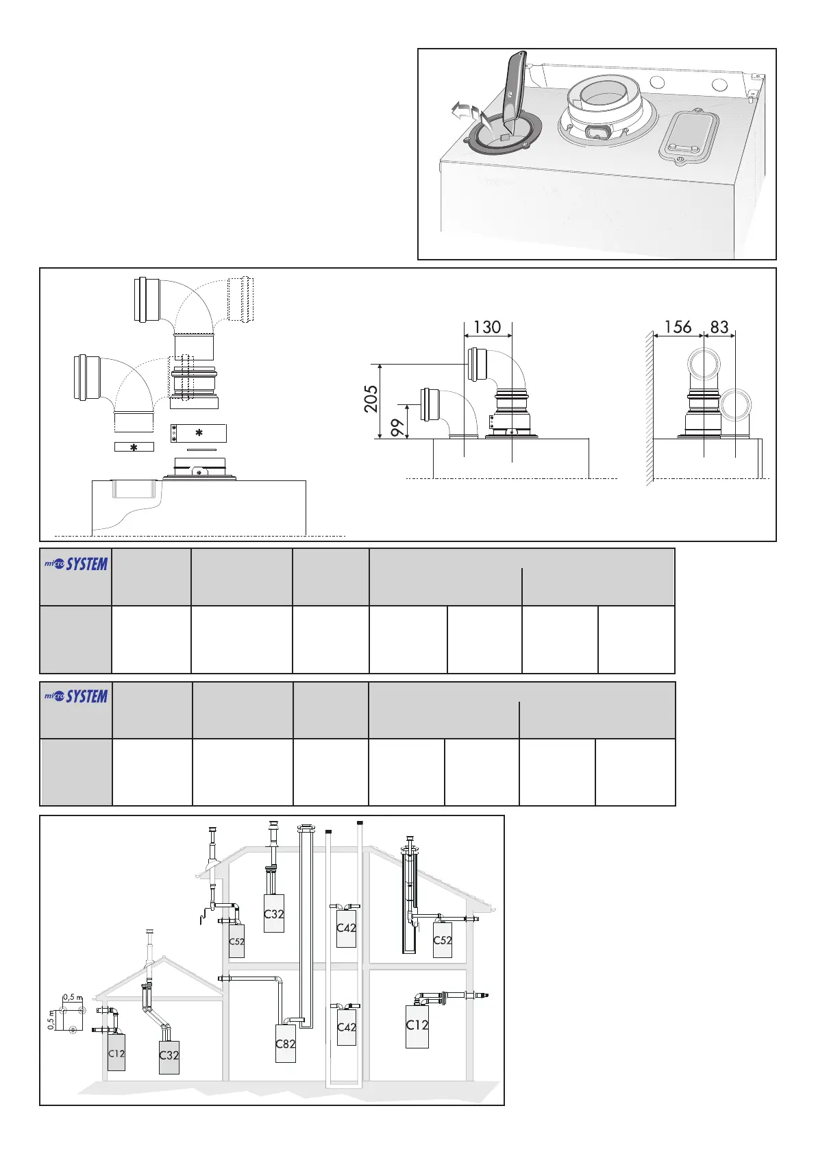
Type
C12 (xx)
C32 (xx)
C42 (xx)
Restrictor
ø 41 mm
L min = 0.5 m
L max = 1 m
Maximum
Extension
Exhaust/Air
L = 5 m
Risk of Condensation Forming
Coaxial
Systems
ø 60/100
Piping not insulated
ø 41 restrictor NO restrictor
NONE NONE
Piping insulated
ø 41 restrictor NO restrictor
NONE NONE
TABLE 2.1
15 RFFI
Exhaust
Type
C12 (xy)
C32 (xy)
C42 (xy)
Restrictor
ø 41 mm
L max = 30 m
Maximum
Extension
Exhaust/Air
78 m
Risk of Condensation Forming
T
win Pipe
Systems
ø 80/80
Piping not insulated
ø 41 restrictor NO restrictor
1.2 m 2.5 m
Piping insulated
ø 41 restrictor NO restrictor
8 m 11.0 m
15 RFFI
TWIN PIPE
SYSTEMS
FIG. 2.10
Ø 80 mm
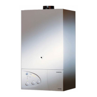
In addition, it is also possible to use a split (twin pipe) system by
fitting a special adaptor to the flue connector and using the
aperture for the air vent intake located on the top part of the
combustion chamber.
To utilise the air intake it is necessary to:
1. Remove the bottom of the air intake by cutting it with a suitable
knife (see
FIG. 2.7);
2. Insert the elbow into the air intake until it reaches the lower
end.
(There is no need to use gaskets or sealing compounds).
10
FIG. 2.8
F
IG. 2.9
In calculating the lengths of the pipes, the
maxim
um length
“L
”
m
ust also tak
e into
consider
ation the v
alues f
or the e
xhaust/air
intak
e end ter
minals
, as well as 90° elbows for
coaxial systems.
 Loading...