9
The boiler is designed to be connected to a coaxial flue discharge system.
In cold or humid weather water vapour may condense on leaving the flue terminal.
The effect of such “steaming” must be considered.
If the terminal is less than 2 metres above a balcony, above ground or above a flat
roof to which people have access, then a suitable terminal guard must be fitted.
When ordering a terminal guard, quote the appliance model number.
A suitable terminal guard is available from:
TOWER FLUE COMPONENTS
Morle
y Road
Tonbridge
K
ent TN9 1RA
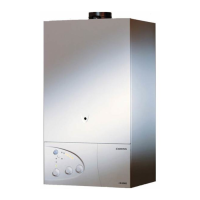
The minimum acceptable spacing from the terminal to obstructions and ventilation
openings are specified in
FIG.
2.5
.
T
ERMINAL
P
OSITION
mm
A - Directly above or below an openable window
or other opening 300
B - Below gutters, solid pipes or drain pipes 75
C - Below eaves 200
D - Below balconies or car-port roof 200
E - From vertical drain pipes and soil pipes 150
F - From internal or external corners 300
G - Above ground or balcony level 300
H - From a surface facing a terminal 600
I
- From a terminal facing a terminal 1200
J - From an opening in the car port
(e.g. door, window) into dwelling 1200
K - Vertically from a terminal in the same wall 1500
L - Horizontally from a terminal in the same wall 300
M - Horizontally from an opening window 300
N - Fixed by vertical flue terminal
FIG. 2.5
Ø 60/100 mm
FIG. 2.6
IMPOR
TANT
!
For all flue systems, a restrictor must
al
ways be inserted into the boiler’s
flue connector; the restrictor must be
Ø 44 in diameter depending on the
length of piping indicated in
T
ABLE
2.1.
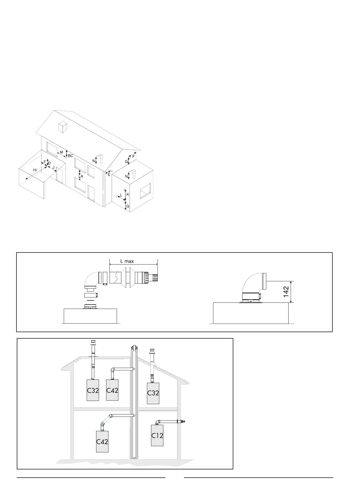
F
IG 2.7 and FIG 2.10 illustrate some of
the v
ar
ious designs f
or coaxial or twin
pipe flue systems
.
For further information on
discharge/ventilation accessories, see
the
FLUE PIPE ACCESSORIES MANU
AL
.
COAXIAL SYSTEMS
FIG. 2.7
 Loading...