2.10 FLUE CONNECTIONS
8
BY-P
ASS
The appliance includes an automatic b
y-pass valve, which protects the
main heat exchanger in case of reduced or interrupted water circulation
through the heating system, due to the closing of ther
mostatic valves or
cock-type valves within the system.
SYSTEM DESIGN
This boiler is suitable only for sealed systems.
DRAIN COCKS
These m
ust be located in accessible positions to permit the draining of
the whole system. The taps must be at least 15mm nominal size an
manufactured in accordance with BS 2870:1980.
SAFETY VALVE DISCHARGE (PRIMARY WATER)
The discharge should terminate facing downwards on the exterior of the
building in a position where discharging (possibly boiling water & steam)
will not create danger or nuisance, but in an easily visible position, and
not cause damage to electrical components and wiring.
The discharge must not be over an entrance or a window or any other
type of public access.
MAINS WATER FEED - CENTRAL HEATING
There must be no direct connection to the mains water supply even
through a non-return valve, without the approval of the Local Water
Authority, and must be in accordance with water supply regulations. Your
attention is drawn to, for GB: Guidance G24.2 and recommendation
R24.2 of the water regulations guide and for IE: the current edition of
I.S.813.
FILLING
A temporary method for initially filling the system and replacing lost water
during servicing and initial filling (complying to current water regulations
and byelaws) is provided. The flexible hose must be removed once the
system has been filled.
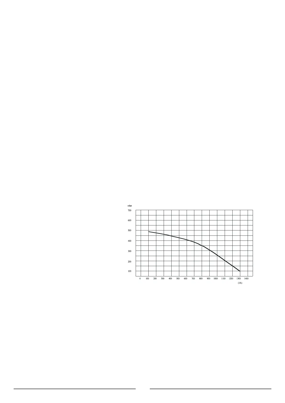
RESIDUAL HEAD OF THE BOILER
FLUE SYSTEM
The pro
vision for satisfactory flue termination must be made as described in BS
5440-1, for IE recommendations I.S.813.
The appliance must be installed so that the flue terminal is exposed to outdoor air,
consideration must be given to terminal discharges onto a pathway or passageway,
check that the combustion discharges will not cause a nuisance and that the terminal
will not obstruct the passageway.
The terminal must not discharge into another room or space such as an outhouse or
lean-to.
It is important that the position of the terminal allows a free passage of air across it at
all times.
If the terminal is fitted within 1 metre of a plastic gutter, within 500mm of a painted
eave or a painted gutter, an aluminium shield of at least 1 metre long should be fitted
to the underside of the gutter or painted surface. An air space of 5mm should be left
betw
een shield and gutter.
The terminal should be located with due regard for the damage or discolouration that
might occur on b
uildings in the vicinity
.
 Loading...