69 / GB
L N
EH1 EH1 ST1 ST1
B T
ANODE
SE TNK BUF
BUS
TA 1 TA 2
B T
IN
AUX 1+24V
30mA
0,5 mm²
T
N
XXA
ON
OFF
N
XXA
N
30mA
T
N
ON
OFF
XXA
N
N
XXA
*
1 ph 3 ph
WARNING
After carrying out the connections between the indoor and outdoor unit, put back both panels of the respective units.
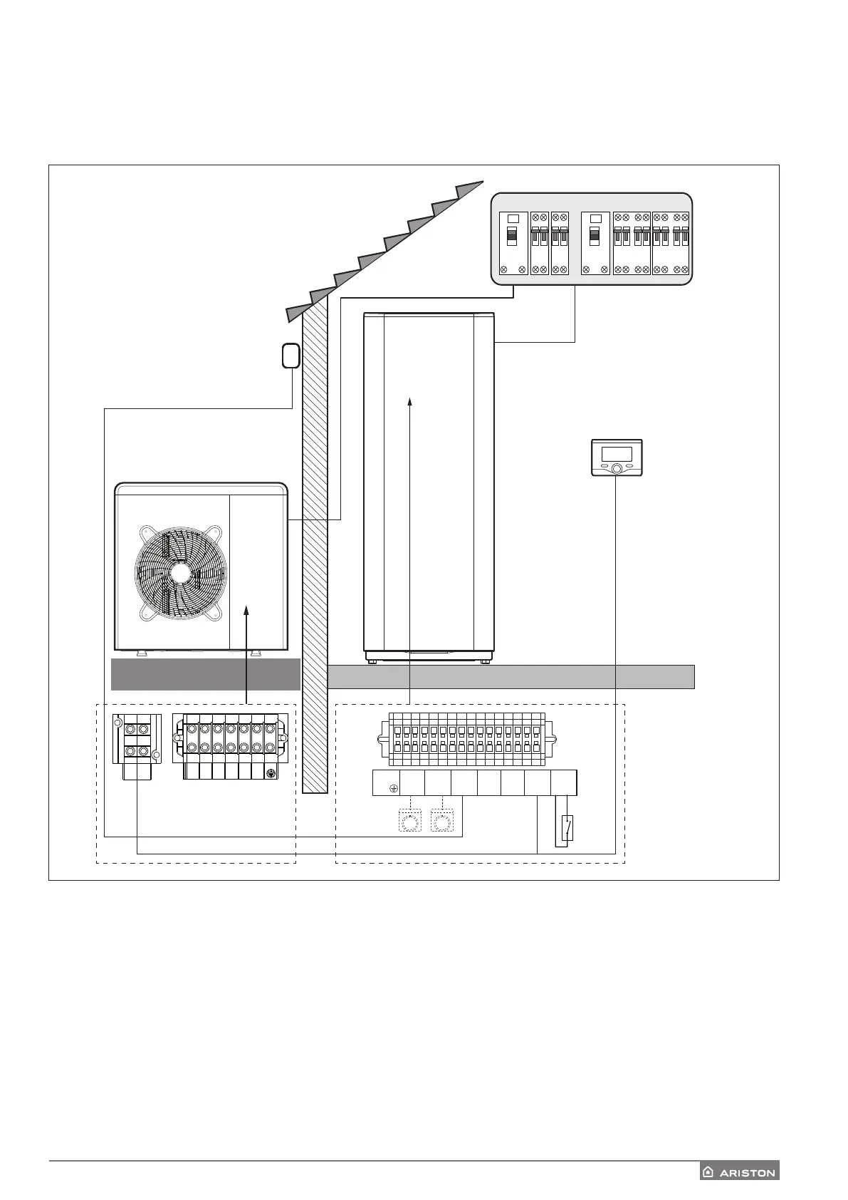
Electrical connections between internal and external unit
Before any work on the system, shut o the power at the breaker. Electrical connections between internal and external units must be perfor-
med using the three low voltage terminals: GND, A, B.
Connect «GND» on the terminal block of the internal unit with «GND» on the external terminal block.
Connect «A+» terminal block on the internal unit with «A» on the external terminal block.
Connect «B-» terminal block on the internal unit with «B» on the external terminal block.
NOTE
It is strongly recommended to verify the presence of a surge protection device (SPD) on main power line and of circuit breakers
connected to the external and internal unit’s control box
* See table of electrical connections
 Loading...