ARITERM SWEDEN AB • ARITERM OY • Asennus ja käyttöohje • Installation och driftanvisning • Installation and operating instruction • 19.11.2009 • 10/32
1
11
8
6
2
5
9
7
3
4
10
12
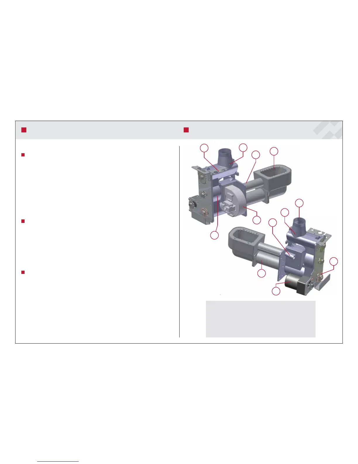
1. Combustion vessel
2. Flame detection system
3. Level switch, receiver
4. Upper connection
5. Level switch, transmitter
6. Blower
7. Auger burner
8. Blocking feeder
9. Drive motor
10. Wheels and chain (not in the figure)
11. Primary air pipe
12. Connector panel
BURNER PARTS
e settings for combustion and burner operation can be found in the Power menu.
Combustion adjustment
In most cases, the factory settings are sufficient for proper and efficient combustion. In addi-
tion, they can be applied when the vacuum in the flue pipe unit is about 18-25 Pa and the pel-
lets used have a diameter of 8 mm. In connection with commissioning, it is recommended that
the values be adjusted by a skilled installer by means of a flue gas analyser. Carbon monoxide
(CO) should be less than 200 ppm and excess air (0
2
) 6.5-8%.
If combustion is poor, the smoke coming from the chimney is black or if the ash produced is
granular, adjust the ratio of fuel to air from the Power menu. Pellet feeding to the burner head
can be adjusted through the High auger and Mean Auger settings. e amount of air required
for combustion can be adjusted through the Max Blower and Mean Blower settings. e Min
settings are not available.
Adjustment example - External auger operating time
e level switches located in the upper connection of the burner measure the amount of pellet
fuel in the burner and control the external storage auger. When the pellet surface drops below
the level switches, the external auger activates (factory setting 30 s). e operating time of the
external auger should be long enough for the pellet surface to rise to the level of the burner up-
per connection. Time can be adjusted from Auger External in the Power menu. If the time is
too long, the pellets rise to the drop pipe level. In this case, pellets may accumulate in the pipe,
which would cause the Pellet Shortage alarm to be given. If the time is too short, there is not
enough time to bring pellets. As a consequence, the same alarm may be given.
Electrical resistance operation
Electrical resistances can be activated from the Burner Adjustments menu by setting the Elec-
trical Resistances setting to 1 if the boiler is equipped with a 6 kW resistance. If a 9 kW resist-
ance is used, set the setting to 3. In this case, 9 kW will be reached in stages (3 kW -> 6 kW
-> 9 kW). e Activation Difference setting is used to determine how much the boiler water
temperature must decrease with respect to the set temperature before the electrical resistances
turn on (Heating method: pellets + electricity). If the burner has malfunctioned or stopped,
the electrical resistance functions as a source of backup heat. If heat is set to be produced only
by means of electricity, the electrical resistance tries to keep the boiler water at the set tempera-
ture. For example, if the temperature difference of the electrical resistance is set to 20 ºC, the
electrical resistance turns on at 58 ºC as long as the set boiler water temperature is 80 ºC. After
heating the water to 62 ºC, the electrical resistance turns off. Settings: Heating method: pellets
+ electricity and Electrical Resistances = 1
BURNER SETTINGS