ARITERM SWEDEN AB • ARITERM OY • Asennus ja käyttöohje • Installation och driftanvisning • Installation and operating instruction • 19.11.2009 • 15/32
0
10
20
30
40
50
60
70
80
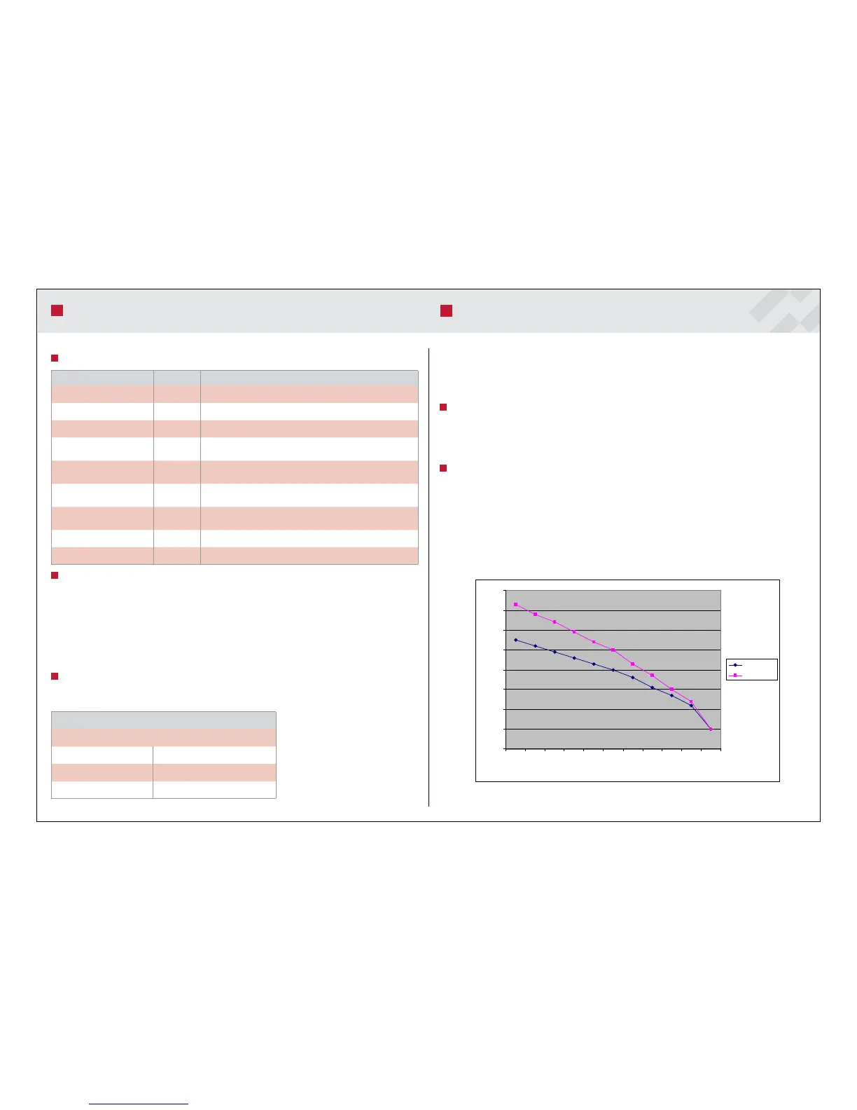
-20 -16 -12 -8 -4 0 4 8 12 16 20
Ulkolämpötila C
Menovesi C
Käyrä 40 C
Käyrä 50 C
Menu Setting Description
Graph 22-56 °C Temperature graph determination (outdoor temperature 0 ºC)
Supply water min 0-30 °C Supply water minimum temperature
Supply water max 30-85 °C Supply water maximum temperature
Compensated graph +5 °C 0-5 °C
Heating circuit graph compensation with an outdoor temperature of
+5 °C
Compensated graph 0°C 0-5 °C
Heating circuit graph compensation with an outdoor temperature of
0 °C
Compensated graph -5°C 0-5 °C
Heating circuit graph compensation with an outdoor temperature of
-5 °C
Room coefficient 0-10 °C
Influence coefficient of the indoor temperature difference on water
supply.
Circulation pump stop Off, 0-40 °C Outdoor temperature at which the circulation pump is stopped.
Drop - Drop menu of the heating circuits
Heat Regulation menu e graph curves more quickly when the outdoor temperature is above +16 ºC. e Supply
Water Max and Min settings can be used to cut the top and bottom of the graph. e angular
coefficient of the graph slightly increases when the Graph setting is increased.
Temperature graph compensation
e graph can be compensated when the outdoor temperature is -5 ºC, 0 ºC and +5 ºC. In this
case, the air may be breezy and humid. If so, the temperature graph might have to be changed.
Compensation also affects the temperature graph of heating circuit 2 in the same way.
Circulation pump control
e Circulation Pump Stop function can be used to determine the outdoor temperature at
which the pump stops. e pump turns on again once the outdoor temperature has decreased
by 3 ºC. However, the circulation pump runs 1 min a day if the outdoor temperature remains
above the set value.
Heating circuit 1 settings
e Heating Circuit 1 Fine Adjustment setting is visible in the main menu if the indoor tem-
perature sensor is not connected. Fine adjustment can be used to raise or lower the entire graph
in the vertical direction (parallel transfer).
NOTE! e Heat Regulation 2 menu appears when supply water sensor 2 is connected. e
compensations and drops specified for heating circuit 1 also apply to heating circuit 2.
Heating circuit 1 settings
e temperature graph can be determined by means of the Graph setting (possible values 22-
56 ºC).
HEATING CIRCUIT SETTINGS
HEATING CIRCUIT SETTINGS
Heating circuit 1 settings
Graph = 40 ºC, Supply water Min = 10 ºC, Supply water Max = 80 ºC
Outdoor temperature 0 ºC Supply water 40 ºC
Outdoor temperature -20 ºC Supply water 55 ºC
Outdoor temperature +20 ºC Supply water 10 ºC
Example 1.
Out door temperature ºC
Supply water 40 ºC
Curve 40 °C
Curve 50 °C