KM-10 User Manual V1.10
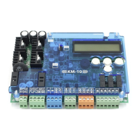
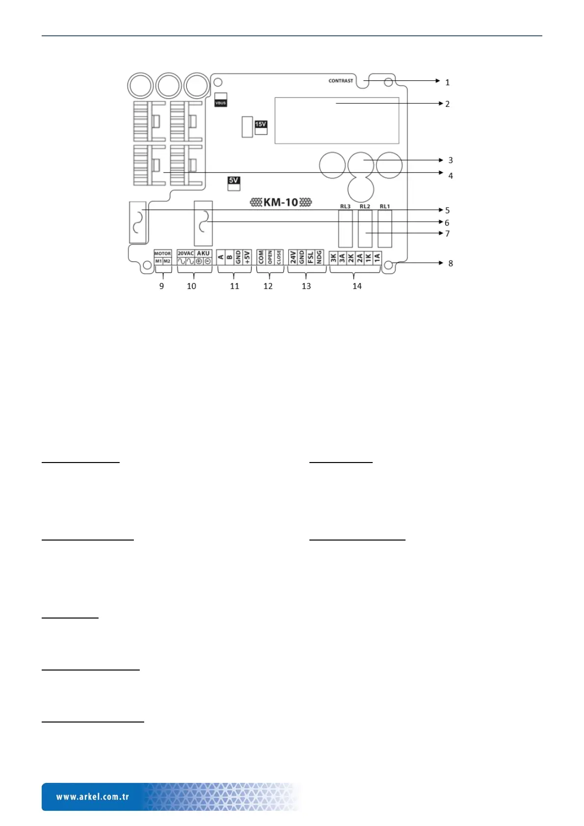
4. Overview of KM-10 Door Controller
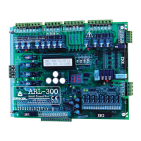
Figure 1 KM-10 layout
1. LCD Contrast adjustment
2. 2x16 character display
3. 4-button keypad
4. Motor driving transistors with coolers
5. AC input supply fuse
6. Battery supply fuse
7. Door is fully open & closed, door re-open (Door
obstruction or photocell) relays
8. Assembly holes
9. Motor output terminals
10. AC power supply and emergency supply terminals
11. Encoder input terminals
12. Door control input terminals
13. Photocell input and NDG input terminals (FSL input
can be used as motor PTC also)
14. Relay output terminals
5. Description of Terminals
Encoder terminals
A: Encoder channel A
B: Encoder channel B
GND: GND
+5V: +5V
Control signals
COM: Common of control signals
OPEN: Open signal
CLOSE: Close signal
Other input terminals
+24V: +24Vdc internal supply for input signals
GND: Ground for internal supply (0Vdc)
FSL: Photocell signal (or motor PTC monitoring input)
NDG: Nudging mode signal
Motor output
MOT : Motor output
: Motor output
Relay output terminals
3A: Reopening (Obstruction or photocell) contact output
(NO)
3O: Reopening contact common
2A: Door closed contact output (NO)
2O: Door closed contact common
1A: Door open contact output (NO)
1O: Door open contact common
AC power supply input
20 VAC : 20 VAC Power supply input
: 20VAC VAC Power supply input
Emergency supply input
AKU +: 24 VDC emergency supply (Battery or supply)
-: 24 VDC