Do you have a question about the Arkel ARCODE and is the answer not in the manual?
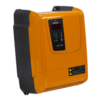
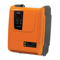
ARCODE control panel dimensions and type can change depending on installation type.
Dimensions of battery pack, required for emergency evacuation with battery.
Dimensions for Type-A and Type-B brake resistors, including mounting hole details.
Diagram showing connections for motor phases, PTC, brakes, fan, encoder, resistor, and batteries.
Diagram illustrating UPS supply outputs and control panel supply inputs.
Illustration showing how to bridge the safety chain terminals.
Illustration for bridging top and bottom limit switches to terminal 100.
Illustration for bridging the car top inspection signal to terminal 100.
Overview of the AREM handset with labeled buttons and functions.
Illustration of the KXCBA CANBus terminal used for connecting the AREM handset.
Diagram showing the recall hand terminal and its activation switch.
Screenshots showing different user access levels in the AREM system.
Screenshot of the 'Device Parameters' settings menu within AREM.
Screenshot of the 'Operating settings' menu, listing basic parameters.
Menu screen for 'Travel Curve Settings', including speed and comfort parameters.
Menu screen for 'Motor encoder settings', covering coupling type and offset.
Menu screen for 'Other Protection Settings', detailing brake monitoring options.
Screenshot of the ARCODE Auto-tune interface.
Starting screen for auto-tune on gearless machines.
Starting screen for auto-tune on geared machines.
Illustration for installing magnets for the SKSR1 bottom limit switch.
Illustration for installing magnets for the SKSR2 top limit switch.
Illustration for installing bar magnets for SML1/SML2 door zone sensors.
Screenshot of the shaft learning interface on AREM.
Screenshots showing the progress stages of shaft learning.
AREM screen display after floor resetting following shaft learning.
Interface for giving calls via COP and LOP using AREM.
Interface for LOP (Landing Operation Panel) learning process.
Screen for selecting LOP learning or LOP reset function.
Screen showing LOP position learning results for each floor.
Interface for updating the LCD picture memory.
Screen for selecting LCD orientation and type for update.
Menu screen showing comfort and performance level settings.
Interface for updating the ARCODE firmware.
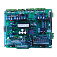
Information on CPC and CPC-T boards for car calls.
Details on SP-16 card settings for parallel installation systems.
List and explanation of various 7-segment messages displayed by ARCODE.
Instructions for clearing permanent errors via system tools.
Troubleshooting for parameter reading errors due to checksum issues.
Troubleshooting for overheating errors in motor or control cabinet.
Troubleshooting for inconsistent encoder speed readings.
| Applicable Standards | EN 81-20, EN 81-50 |
|---|---|
| Maximum Number of Floors | 64 |
| Safety Circuit Voltage | 24V DC |
| Shaft Learning | Yes |
| Power Supply | 3-phase, 380V AC, 50/60Hz |
| Connection | Terminal blocks |
| Buttons | Not applicable |
| Analog Sticks | Not applicable |
| Vibration | Not applicable |