Arkel Elektrik Elektronik San. ve Tic. A.Ş. www.arkel.com.tr
ARKEL 40 ARCODE
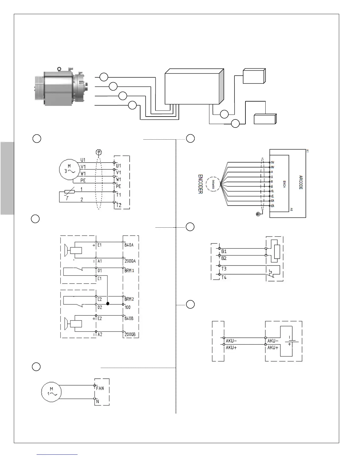
Step-2: Motor connections
Make the connections of motor phases & motor PTC, brakes & brake release contacts, motor fan, encoder,
brake resistor and battery pack with UPS (if required).
: Motor phases & motor PTC connections
: Brake & Brake checkback microswitches
connections
: Brake resistor connections
: Batteries connections (If required)
Figure-4: Motor, brake, fan, encoder, brake resistor and batteries connections
! you can find connections in
electr
ical drawing which is suitable
for your encoder
***Motor does not has PTC
you must bridge T1 and T2
***Brake Resistor does
not has PTC you must
bridge T3 and T4