Arkel Elektrik Elektronik San. ve Tic. A.Ş. www.arkel.com.tr
ARKEL 39 ARCODE
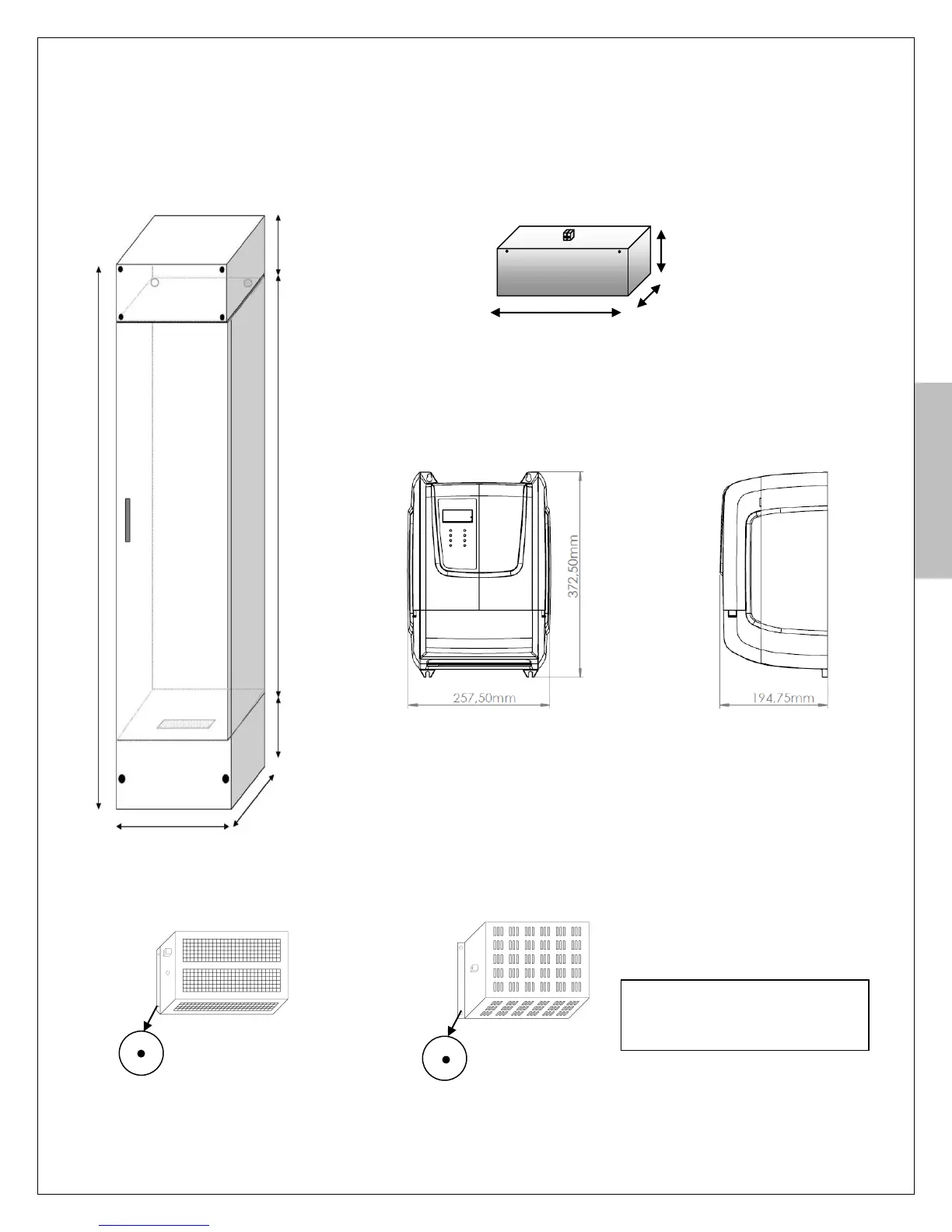
Step-1: Mechanical installation
Mount ARCODE control cabinet, brake resistor, battery pack and UPS (if required) to their places.
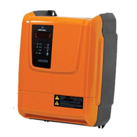
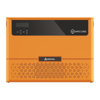
Figure-2a: ARCODE control panel(Control panel
dimensions and type can change depending on
installation type.
Figure-3: Type-A and Type-B dimensions of brake resistors
Warning: Mount the brake resistor
horizontally! Don’t mount it on
control panel.
Figure-1: Dimensions of battery pack (it is required only when
the inverter is supplied with battery during emergency evacuation)
(it is not used for brake relase emergency evacuation)