Do you have a question about the Arkel ARCODE 4B26A and is the answer not in the manual?
Product conformity with generic standards for industrial environments, emission, and harmonic currents.
Crucial safety precautions for device operation, handling, and installation to prevent damage or injury.
Manual redistribution is prohibited; violations will be prosecuted and lead to indemnity.
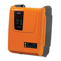
Introduction to the Arcode device and its primary functions in elevator systems.
Detailed list of the Arcode's advanced functionalities and capabilities for elevator control.
Guidance on identifying the Arcode model and checking essential information on the nameplate.
Details on optional boards including ENCA, ENCI, and Door Bridging for enhanced functionality.
Specifications for optimal Arcode installation environment, covering area, temperature, and humidity.
Detailed physical dimensions for B size and C size Arcode case mechanics.
Recommendations for vertical installation orientation and spacing, considering EMC compatibility.
Step-by-step instructions for installing optional boards and the SD card into the Arcode unit.
Comprehensive technical specifications for the Arcode driver and controller, including power, current, and communication.
Diagrams and instructions for connecting power supply, motor, brake resistor, and emergency supply to the driver.
Connecting the 3-phase AC main power supply to the Arcode driver terminals, emphasizing wire thickness and shielding.
Direct connection of the motor to the Arcode using shielded, high-current capable cables.
Proper connection of the appropriate brake resistor to the designated terminals on the Arcode.
Connecting emergency power sources like DC batteries or UPS for continuity during power loss.
Guidelines for connecting incremental and absolute encoders, emphasizing cable shielding and routing.
Overview of Arcode controller connections, detailing IO board and CPU board interfaces for inputs, outputs, and communication.
Connecting safety circuit door contacts for monitoring and bridging, supporting 220VAC or 48VAC circuits.
Connecting magnetic switches for detecting floor zones, utilizing isolated input structure.
Details on the two CAN bus networks for shaft and cabinet communication.
Information on the three serial RS485 ports for future use and group communication.
Connecting Arcode's 16 optically isolated logic inputs for programmable functions.
Connecting Arcode's 4 open collector outputs for programmable functions with a 200mA current limit.
Details on the 5 programmable relay outputs (dry contacts) for various control functions.
Connecting the motor thermostat for continuous monitoring and motor protection.
The Arcode is an integrated elevator control unit designed by Arkel Elektrik Elektronik Tic. Ltd. Şti. It combines the functions of a lift system controller, a main motor drive, and an evacuation system for power loss conditions. The device is available in various models, including 4B14A, 4B17A, 4B26A, 4C35A, 4C50A, and 4D75A, with different power capabilities and casing sizes (B, C, and D).
The Arcode primarily serves three main functions:
| Brand | Arkel |
|---|---|
| Model | ARCODE 4B26A |
| Category | Control Unit |
| Language | English |