Page 17 of 18
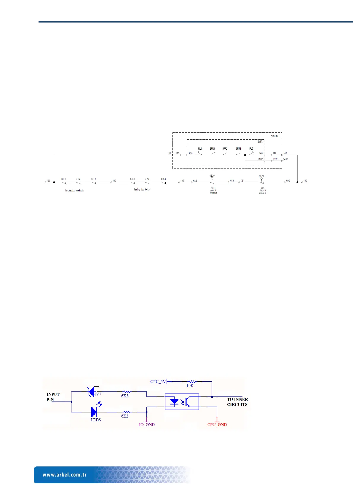
4.3.1 Safety Circuit Connection
Door contacts of the safety circuit need to be connected to the Arcode for 2 reasons. First safety
circuit door contacts monitoring and second is the bridging of the door contacts for re-leveling or
pre-opening. These terminals are fully isolated and can operate with 220VAC or 48VAC safety
circuits.
For door bridging function optional door bridging board should be installed. All signals are routed
internally to the door bridging board.
4.3.2 ML1-ML2 Magnetic Switches Inputs
Magnetic switches to detect floor zones magnets are connected to these inputs. Those inputs are
also designed in isolated structure.
4.3.3 Can-Bus Connection
The Arcode contains 2 separate can bus network connection. One can bus network is used to control
and power LOPs beyond the shaft while other is used to control cabinet functions.
4.3.4 Serial RS485 Ports
There are 3 serial RS485 ports are designed in Arcode main system. 2 serial ports; 1 half duplex and 1
full duplex are located on IO board while 1 full duplex serial port is located on main CPU board.
Half duplex serial port on the IO board is reserved for group communication feature while others are
reserved for future use. Parameters for those serial communication lines are application depended
and not defined to any default value.
4.3.5 Programmable Inputs Connection
Arcode has 16 logic inputs whose functions are programmable. Each input is designed in a optically
isolated topology and reference circuit for each input line is presented below for right usage.