Page 14 of 18
4.2 DRIVER SIDE CONNECTIONS
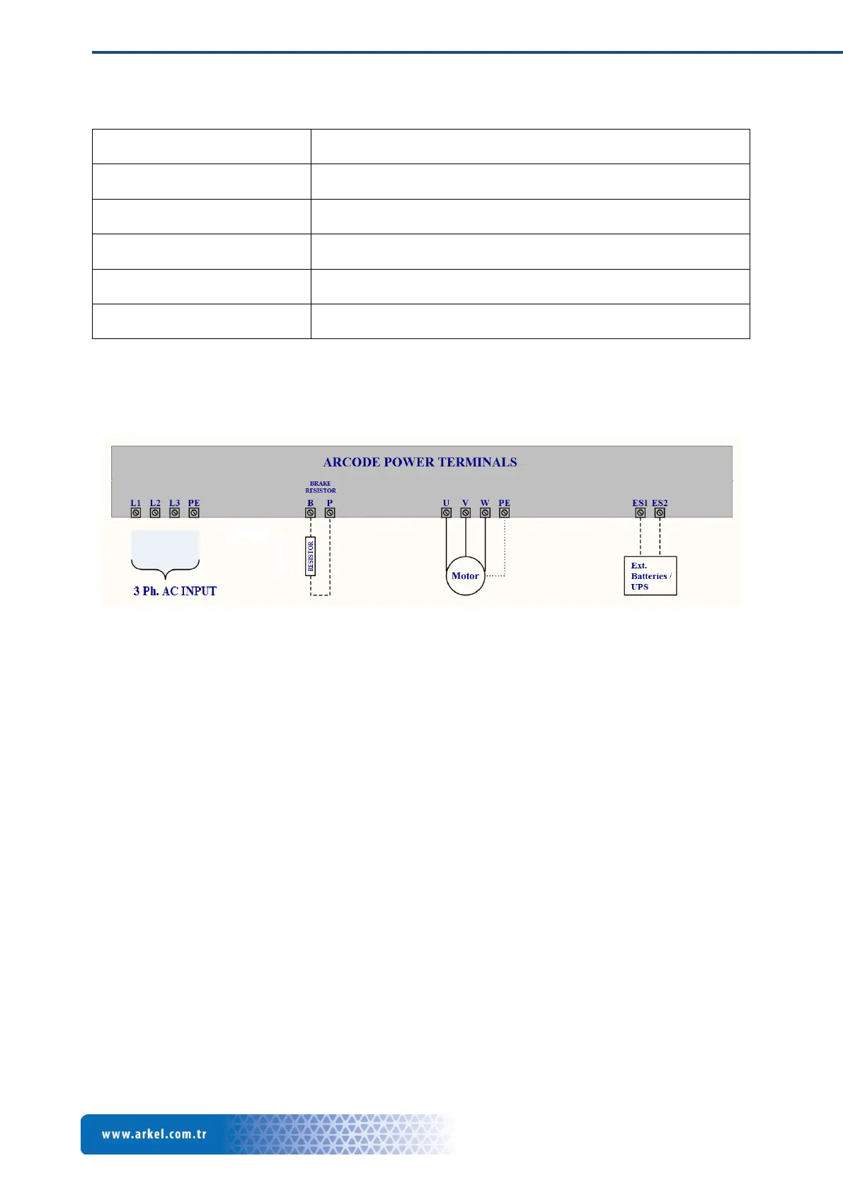
4.2.1 Main Supply Connection
Main power supply for the lift system is connected to first 4 terminals on the Arcode. Power supply
needs to be 4 wires with 3 phases and an earth. Wire thickness should be chosen according to
calculated maximum current flow through the cable. Additionally phase wires should be connected
directly to Arcode without any joint. To prevent cable emission from supply cable, a shielded cable
should be used.
EMC filter and line switches are already included in the Arcode device. External filter usage is not
necessary.
4.2.2 Motor Connection
Motor connection to the Arcode should be direct connection without any joint. Additionally enough
current capable shielded cables must be used. For the thickness of the cables please refers to
international standards.
4.2.3 Brake Resistor Connection
Appropriate brake resistor needs to be connected to the terminals.
4.2.4 Emergency Supply Connection
For any power loss condition emergency supply can be used via these terminals. Emergency supply
can be 60V DC (5 x 12 V batteries) or UPS device (220V AC) which capable to feed motor. Emergency
supply connection switches are already installed in the Arcode so external switches are not required.
4 programmable transistor outputs(open collector Imax:200mA)
Door bridging board connector (reserved)
Air ventilation and aluminum cooler
4 digit seven segment plus 8 LED indicator