KM-10 User Manual V1.10
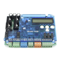
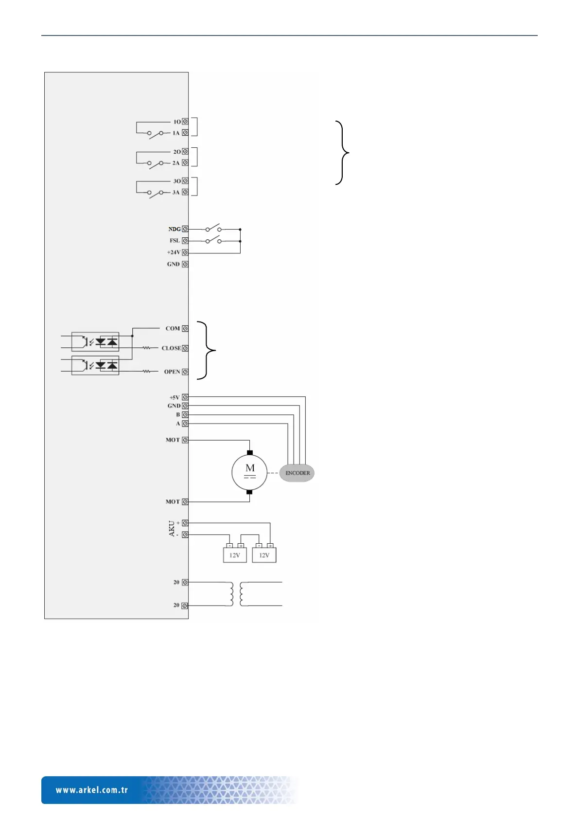
7. Connection Diagram
Figure 3 Connection diagram
Outputs to lift control mainboard
(Max. 3A @ 250VAC or 30VDC)
Note: The relay contacts must not be used
as safety contact in the safety circuit of the
elevator!
Photocell signal input (or Motor PTC input)
(Inputs are activated with 24VDC internal supply)
*If FSL input is used as motor PTC the signal must be active
during normal operation. If signal is interrupted KM-10 gives
PTC error.
Inputs from lift control system
Can be supplied with internal or external 24Vdc.
Refer to Figure-4 and Figure-5
Note: For V1.9 and higher version controllers, positive or negative
common is selectable.
+5Vdc operation voltage
100-2048 pulse
2-channel encoder
24V DC geared motor, maks.
8A
24V DC emergency supply
(With 2 pcs. 12V/1.2Ah battery or
external supply)
Min. trans. power = 10VA + motor power
 Loading...