THE PROCESS
Holding Tube
Circulation
Pump
T4
Back Pressure Valve
Cooling
Section
Feed
Pump
P
T3
SSR
3 Term Controller
T1
Feed
Vessel
T2
Pressure
Pressure
Heating
Section
Cooling Water
Flow Control
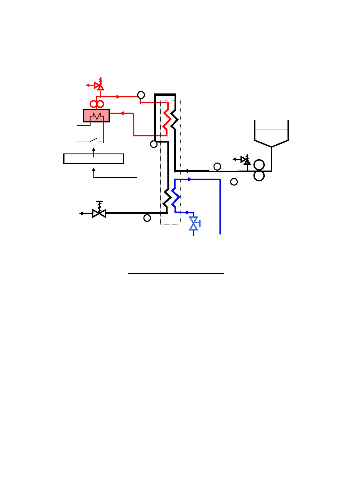
Simplified Process Flow Diagram
(not showing pre-heat or re-generation stages)
The product to be processed is pumped from the Feed Vessel to the Heat Exchanger
by the Feed Pump. A Pressure Relief Valve protects the Heat Exchanger from
excessive pressure build up. Sensors measure the temperature and pressure of the
product before it enters the Heat Exchanger.
In the Heating Section of the Heat Exchanger the product is heated to the process
temperature by pressurised hot water. Note, for the purpose of simplicity, the above
diagram does not show the pre-heat section of the heat exchangers. The Plate Heat
Exchanger (FT74P) includes a re-generation stage, where the hot outgoing product is
used to pre-heat the incoming product. The Tubular Heat Exchanger (FT74T) uses
some of the pressurised hot water at a lower flow rate to pre-heat the product in a
dedicated pre-heat section. This is described in more detail in the Description section.
The pressurised hot water is generated by an electric heater contained in a heating
vessel. A pump circulates the hot water through the heat exchanger and back to the
pressurised heating vessel. A pressure relief valve provides protection against excess
pressure.
6