installation &
operating instructions
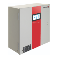
ips 4000 controller - Integrated pumping
system for variable primary applications
23
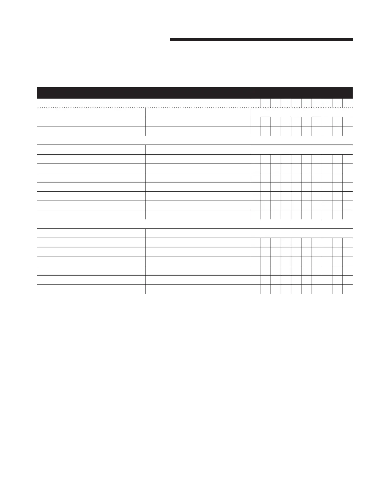
5.0 ips 4000 control system service lifecycle
manufacturer's suggested maintenance schedule and component life year after installation
1 2 3 4 5 6 7 8 9 10
software and settings maintenance
All firmware As required by manufacturer
ü ü ü ü ü ü ü ü ü ü
Optimization logic & control programming As service packs as released by Armstrong
ü ü ü ü ü ü ü ü ü ü
panels & pc/touchscreen
Integrated pc & touchscreen Replace pc & touchscreen
ü
plcs Check and confirm voltage
ü ü ü ü ü ü ü ü ü ü
plcs and associated components Replace
ü
Power supply Check and confirm voltage
ü ü ü ü ü ü ü ü ü ü
Power supply Replace on failure
Panel integrity (gasket, terminals, glands…) Inspect and repair as needed
ü ü ü ü ü ü ü ü ü ü
Panel filter (when included) Inspect and clean as needed
ü ü ü ü ü ü ü ü ü ü
sensors
Water temperature sensor(s) Confirm accuracy
ü ü ü ü ü ü ü ü ü ü
Water temperature sensor(s) Full calibration
ü ü ü
Water flow sensor Confirm accuracy
ü ü ü ü ü ü ü ü ü ü
Water flow sensor Full calibration
ü ü ü
Pressure dierential sensor(s) Confirm accuracy
ü ü ü ü ü ü ü ü ü ü
Pressure dierential sensor(s) Full calibration
ü ü ü
notes
• As with any system the component life expectancy varies
according to usage and operating conditions.
• Components operating inside of a clean and weather con-
trolled environment will typically last longer than compo-
nents exposed to the elements or otherwise operating in
dirty environments.
• Component life expectancy also varies according to the
power quality (absence of harmonic distortion) and consis-
tency of voltage supplied to the device.
 Loading...