installation &
operating instructions
ips 4000 controller - Integrated pumping
system for variable primary applications
6
3.0 operation displays
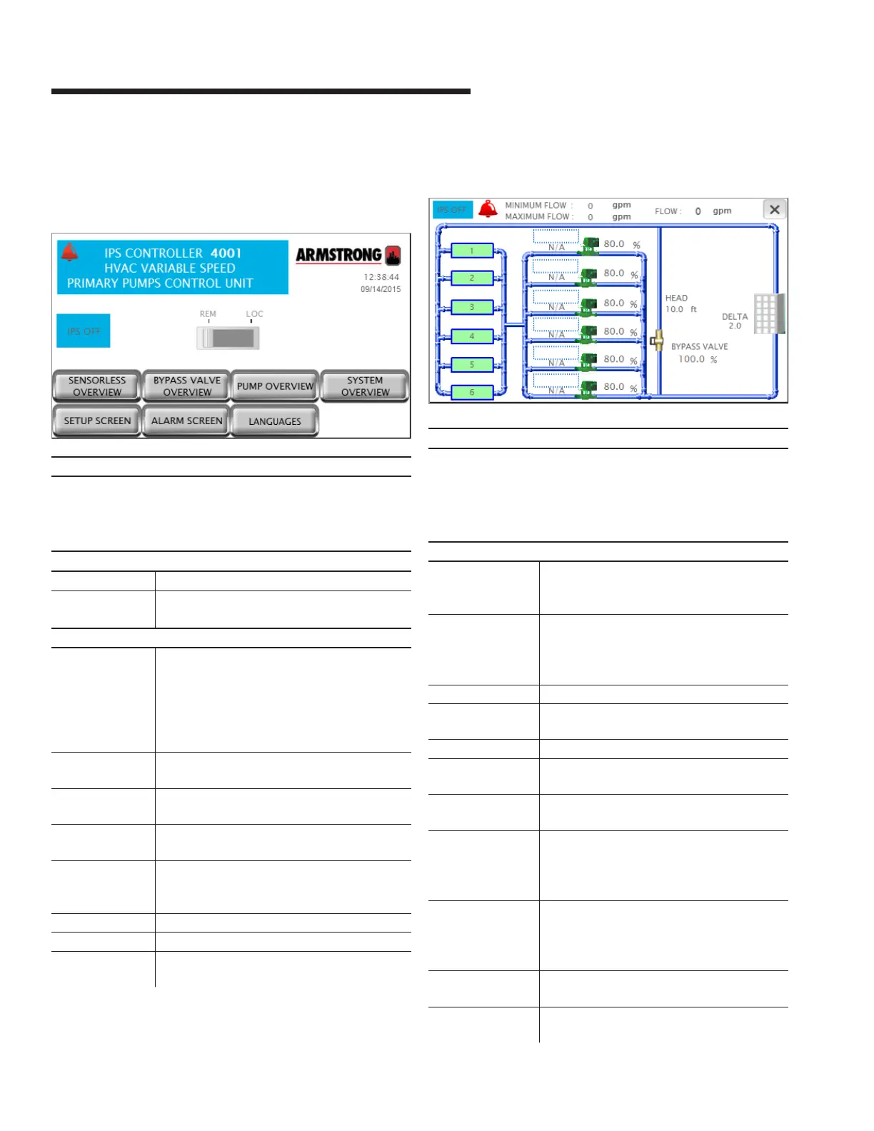
3.1.0 main menu
Description
This is the screen the operator sees when powering up the
unit. It indicates status of the system’s most important vari-
ables, and also provides a means for the user to navigation to
all system screens
Data
ips status Indicates if the ips is on or o
Alarm If there is an alarm in the system, a red bell
appears at the top left corner
Buttons
rem – loc Slider button that allows changing the ips
mode to remote or local.
Local will turn on the ips immediately. Remote
causes the ips to follow the bas signal
(hard wired or serial communication) to turn
on or o
zone overview Changes the screen to Zone Overview. Not
available if the vfd type is ivs sensorless
bypass valve
overview
Changes the current screen to Bypass valve
Overview
system
overview
Changes the current screen to System
Overview
sensorless
overview
Changes the current screen to Sensorless
Overview. Only available if the sensorless
control is enabled
setup screen Navigates to the setup menu level zero screen
pump overview Navigates to the Pump Overview screen
alarm screen Shows the alarm screen. If there is an active
alarm, this button turns red
3.1.1 system overview
Description
Shows a detailed view of the system. The screen adapts to the
configuration of the system by showing the number of pumps
and chillers/boilers, the system flow , bypass valve, zone PVs
or head and flow. Press the x on the top right corner to go back
to the previous screen
Data
Chiller/boiler
1 to 6 status
The icons show the device status:
grey – stopped
green – running
Pump 1 to 6 status The pump icons shows the pump status:
grey – stopped
green – running
red - alarm
Pump 1 to 6 mode Shows each pump mode: Hand, O or Auto
Pump 1 to 6 duty Shows each pump duty: Duty1, Duty2, Duty3,
Duty4, Duty5, Duty6 or Stand-by
Pump 1 to 6 speed Shows each pump speed in percentage
active zone Indicates which zone is assigned as Active.
Not visible if the vfd type is ivs sensorless
deviation Indicates the active zone deviation. Not vis-
ible if the vfd type is ivs sensorless
setpoint Indicates the active zone setpoint in the
chosen units. Not visible if the vfd type is ivs
sensorless and also system valves control is
disabled
max open vlv Indicates the opening of the driving sys-
tem valve. Not visible if the vfd type is ivs
sensorless and also system valves control is
disabled
flow Indicates both sensor and sensorless flow
values in the system based on the selection
head Indicates the total head in the system. Only
visible if the vfd type is ivs sensorless