Do you have a question about the Armstrong 4000 and is the answer not in the manual?
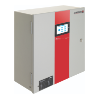
Procedures for installing the IPS controller, including power supply connection.
Specifies operating temperature and humidity ranges for the controller.
Ensures field devices are properly installed and wired before controller configuration.
Details communication protocols and wiring for connecting the IPS controller to a BAS.
The initial screen displaying system status and navigation options.
Detailed system view showing pumps, chillers, flow, bypass valve, and zone status.
Displays system zones, including actual values, setpoints, and status.
Provides information on pump status, mode, speed, and run hours.
Displays sensorless-specific pump data and status, available for compatible drives.
Allows detailed control and monitoring of individual pumps, including mode, speed, and alarms.
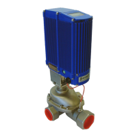
Monitors the status and operation of the bypass valve.
Screen for resetting the auto bypass function for the VFD.
Displays current system alarms, allowing acknowledgment and investigation.
Shows a log of past alarm events with timestamps and descriptions.
Displays the status of the PLC and software revisions.
Navigation screen for accessing various configuration settings at Level 2 access.
Configures system zones, including the number of zones and engineering units.
Configures pump parameters like number of pumps, standby pump, and switch time.
Sets minimum, maximum, and default pump speeds, as well as ramp settings.
Configures parameters for sensorless operation, including flow and head settings.
Configures End of Curve (EOC) protection settings using DP or flow sensors.
Defines conditions for staging pumps up or down based on speed and delay timers.
Configures PID loop parameters for pump speed control.
Sets the system clock for date and time.
Configures bypass valve operation, including PID settings and setpoints.
Configures communication parameters for connecting to a Building Automation System.
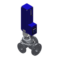
Configures control parameters for system valves.
Configures how VFD readouts (amps, flow, volts, head, power) are displayed.
Configures flow source, range, and limits for the system.
Configures minimum and maximum flow limits for individual chillers or boilers.
| Brand | Armstrong |
|---|---|
| Model | 4000 |
| Category | Controller |
| Language | English |