installation &
operating instructions
ips 4000 controller - Integrated pumping
system for variable primary applications
19
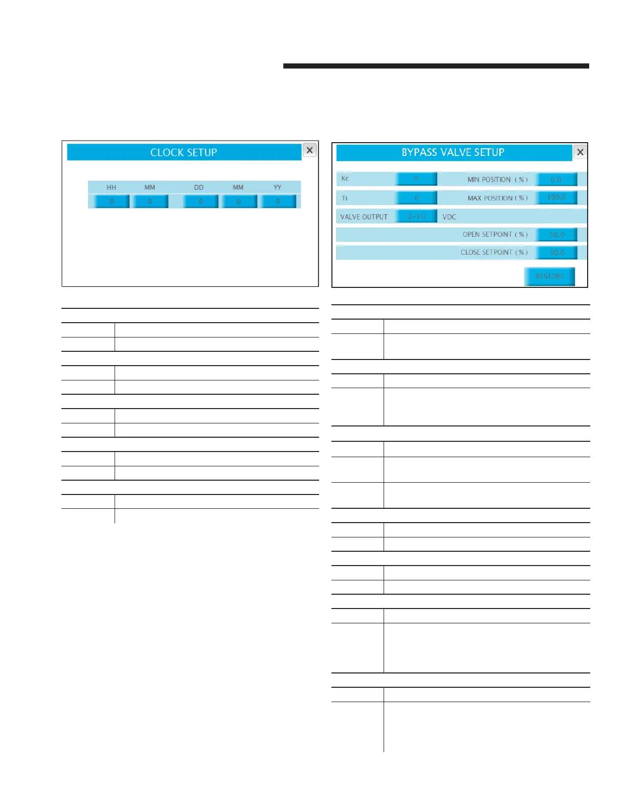
4.1.9 clock setup
Parameter: hh
Range: Function:
0 - 24 Sytem clock hour
Parameter: mm
Range: Function:
0 - 60 Sytem clock minute
Parameter: dd
Range: Function:
1 - 31 Sytem clock day
Parameter: mm
Range: Function:
1 - 12 Sytem clock month
Parameter: yy
Range: Function:
00 – 99 Sytem clock year
4.1.10 bypass valve setup
Parameter: Kc
Range: Function:
0-9999 Determines the valve control pid loop gain. Smaller
values correspond to a more responsive controller
Parameter: Ti
Range: Function:
0-999 Determines the valve control pid loop integral time.
Larger values correspond to more iterations and
reduction of steady state error
Parameter: valve output
Options: Function:
0 – 10 vdc 0 vdc commands the valve as fully closed. 10 vdc as
fully open
2 – 10 vdc 2 vdc commands the valve as fully closed. 10 vdc as
fully open
Parameter: minimum position
Range: Function:
0.0 - 100.0 Minimum position the valve is allowed to
Parameter: maximum position
Range: Function:
0.0 - 100.0 Maximum position the valve is allowed to
Parameter: open setpoint
Range: Function:
0.0 - 100.0 When system flow is under the chiller/boiler
minimum and the bypass valve is open at this
percentage (or above), the pumps will ramp up to
maximum speed
Parameter: close setpoint
Range: Function:
0.0 - 100.0 When the system flow is under the chiller/boiler
minimum and the bypass valve is closing and
reaches this percentage (or below) the pumps
return to their normal speed
 Loading...